Product description en
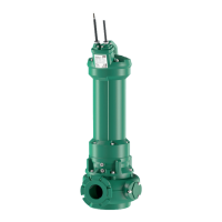
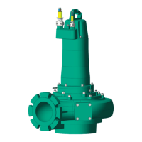
Installation and operating instructions Wilo Motor HC 20.1 + EMU FA, Rexa SUPRA, Rexa SOLID 11
The hydraulics are not self-priming, in other words, the fluid must flow in either auto-
matically or with supply pressure.
Impeller shapes
The individual impeller shapes depend on the size of the hydraulics and not every im-
peller shape is available for every hydraulic system. The following is an overview of the
different impeller shapes:
ƒ Vortex impeller
ƒ Single-channel impeller
ƒ Two-channel impeller
ƒ Three-channel impeller
ƒ Four-channel impeller
ƒ SOLID impeller, closed or half open
Inspection cover (depending on the hydraulics)
Additional opening on the hydraulics housing. This opening is used to remove clogging
in the hydraulics.
Casing and impeller wear rings (depending on the hydraulics)
The suction port and impeller are subjected to the most stress when pumping. In the
case of channel impellers, the gap between the impeller and the suction port is an im-
portant factor for a constant efficiency. The larger the gap between the impeller and
the suction port, the higher the losses in the delivery rate. The efficiency decreases and
the danger of clogging increases. In order to ensure long and efficient operation of the
hydraulics, an impeller wear ring and/or casing wear ring is installed depending on the
impeller and the hydraulics.
ƒ Impeller wear ring
The impeller wear ring is attached to the channel impellers and protects the incom-
ing flow edge of the impeller.
ƒ Casing wear ring
The casing wear ring is installed in the suction port of the hydraulics and protects
the incoming flow edge in the centrifugal chamber.
The two components can be replaced easily when worn.
4.1.2 Motor
In the three-phase current version, self-cooling submersible motors are used as the
drive. The motor can be used in continuous duty both immersed and non-immersed.
Continuous duty is also possible in dry well installation. The roller bearings are perman-
ently lubricated, which means they are maintenance-free. The connection cable is lon-
gitudinally watertight and has bare cable ends.
4.1.3 Cooling system
The motor has an active cooling system with separate cooling circuit. The water-glycol
mixture P35 is used as coolant. Coolant circulation is performed by an impeller. The im-
peller is driven with a magnetic coupling by the motor shaft. The waste heat is trans-
ferred directly to the fluid via the cooling flange. The cooling system is not pressurised
when in cold state. A built-in overpressure valve limits the max. pressure to 3bar in the
event of a fault.
CAUTION!The overpressure valve is only fitted as standard from year of manufac-
ture 2015 onwards. In the case of motors without an overpressure valve, extremely
high pressure can occur in the cooling system if there is a fault. It is imperative that
a conversion is made! Please contact customer service for the conversion!
4.1.4 Seal
Different methods are used for the seal to the fluid and the motor compartment:
ƒ Version “G”: two separate mechanical seals
ƒ Version “K”: two mechanical seals in a block seal cartridge made of stainless steel
Leakage from the seal is caught in the sealing chamber or leakage chamber:
ƒ The sealing chamber accommodates any possible leakage of the seal on the fluid
side.
ƒ The leakage chamber accommodates any possible leakage of the seal on the motor
side.
The sealing chamber between the mechanical seals is filled with medical white oil. The
leakage chamber is empty.
4.1.5 Material
The following materials are used in the standard version:
 Loading...