English
39WILO SE 09/2013
7.2 Description (Fig. 1, 2, 5, 6, 7, 8)
1 - Strainer-foot valve
2 - Pump suction valve
3 - Pump discharge valve
4 - Non-return valve
5 - Venting and filling plug
6 - Drain-priming plug
7 - Pipe supports or brackets
8 - Strainer
9 - Storage tank
10 - Town water supply
11 - Disconnecting switch with fuses
12 - Lifting hook
13 - Foundation block
14 - Cock
15 - Pressure sensor
16 - Tank
17 - Insulation valve of the tank
18 - Switch block
19 - Pump identification sticker
BP - By-pass
HA - Maximum suction head
HC - Minimum inlet pressure
7.3 Installation
Two standard types.
Fig. 1: pump in suction
Fig. 2: pump in load on storage tank (item 9) or
town water supply (item 10).
- Install the pump in a place easy to reach, pro-
tected against frost and as close as possible from
the drawing point.
- For heavy pumps provide a point of attachment
(lifting hook) in the pump axis (item 12) to facili-
tate removal.
- Install the pump on a concrete block (at least 10
cm high) (item 13) and fix with anchor bolts
(installation plan see Fig. 3).
- Foresee an insulating material under the concrete
block (cork or reinforced rubber) to avoid any
noise and vibration transmission into the installa-
tion.
- Before final tightening of anchor bolts, ensure that
the pump axis is vertical: use shims if necessary.
NOTE: Keep in mind
that the altitude of the
installation place and
the water temperature
may reduce the suction
possibilities of the
pump.
NOTE: Beyond 80° C,
plan to install the pump
in load.
CAUTION! Danger of material damage!
The installation has to bear the pressure reached
when the pump runs at maximum frequency and
zero flow rate.
- Pump with oval flange pump casing : with
threaded screw-on tubes directly on the tapped
oval counterflanges delivered with the pump.
- Pump with round flange pump casing: with
weld-on or screw-on tube in the counterflanges
(counterflanges available as accessories).
- Pump casing with rapid hose coupling : with a
bracket, to be installed with an end to be fixed
on the pipe (bracket and threaded end available
as accessories).
- The diameter of the pipe must never be smaller
than the one of the counterflange.
- Pumps series 400, 800, 1600/6: the direction of
the fluid flow is indicated on the pump identifi-
cation sticker.
- Pumps series 2200, 7000, 9500: an arrow on the
pump casing shows the direction of the fluid
flow.
CAUTION! Danger of material damage!
Connections have to be correctly sealed, no air
entrance is allowed on the suction pipe which
shows a minimum mounting declivity of 2% (Fig.
1).
- Limit the length of the suction pipe and avoid all
features that cause losses of head (bends, valves,
tapers).
- Use supports or collars (Fig. 1, 2, item 7) so that
the pump does not bear the weight of the pipes.
CAUTION! Danger of material damage!
When the pump is in load, it is recommended to
connect the non-return valve to the pump dis-
charge to protect it against hammer blow effects.
NOTE: To pump water with a large content of air
or hot water, we recommend to install the
bypass kit (Fig. 1, item BP). Mount the pressure
sensor on the discharge pipe (Fig. 7).
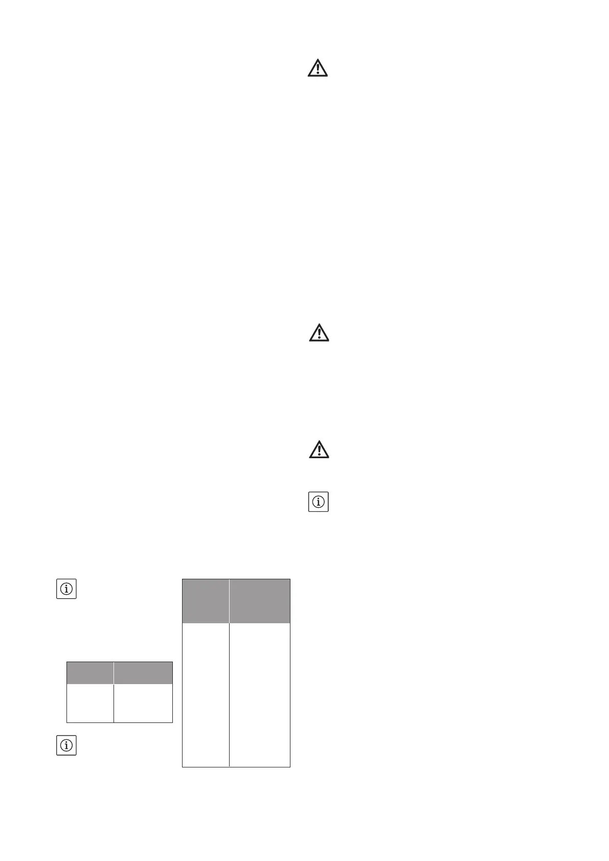
Altitude Loss of head
0 m 0 mCL
500 m 0,60 mCL
1000 m 1,15 mCL
Tempe-
rature
Loss of head
20°C 0,20 mCL
30°C 0,40 mCL
40°C 0,70 mCL
(50°C) 1,20 mCL
(60°C) 1,90 mCL
(70°C) 3,10 mCL
(80°C) 4,70 mCL
(90°C) 7,10 mCL
(100°C) 10,30 mCL
(110°C) 14,70 mCL
(120°C) 20,50 mCL
 Loading...