Do you have a question about the Wilo Wilo-Para 15-130/7-50/SC-12/I and is the answer not in the manual?
These installation and operating instructions are an integral part of the product. Read carefully and keep accessible.
Describes how safety instructions are displayed with signal words and symbols for personal injury and property damage.
Defines DANGER!, WARNING!, CAUTION!, and NOTICE signal words for safety instructions.
Lists common symbols used in the instructions, such as electrical voltage, general danger, hot surfaces, and magnetic fields.
Specifies requirements for personnel, including instruction on regulations and electrical work by authorised electricians.
Defines a qualified electrician as a person with technical training, knowledge, and experience to identify electrical hazards.
Details requirements for electrical work, including disconnection, RCD protection, earthing, and cable replacement.
Outlines operator responsibilities, including qualified personnel, guarding against hazards, and replacing defective parts.
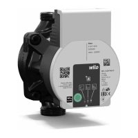
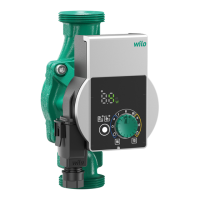
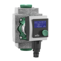
Lists and describes the main components of the Wilo-Para pump as shown in Fig. 1.
Explains the function of the high-efficiency circulator for hot-water heating systems with integrated differential pressure control.
Explains the coding system used in the Wilo-Para model numbers and their meanings.
Describes the meaning of LED indicators for signal display, control mode, and pump curves.
Details the functions of the operating button for selecting control modes, pump curves, and special functions.
Recommended for two-pipe heating systems to reduce flow noise at thermostatic valves.
Recommended for underfloor heating and other applications requiring constant delivery head irrespective of flow.
Recommended for systems with fixed system resistance requiring a constant volume flow.
Explains how the pump speed is controlled by an external controller using a PWM signal.
Describes iPWM 1 mode where pump speed is controlled by PWM input signal. Includes cable break behaviour and signal input details.
Describes iPWM 2 mode where pump speed is controlled by PWM input signal. Includes cable break behaviour and signal input details.
Explains how to activate the pump venting function via the operating button.
Initiates a manual restart by pressing and holding the operating button for 5 seconds.
Activates key lock by holding button for 8 seconds to prevent setting changes.
Activates factory settings by holding the operating button while switching off the pump.
Specifies permitted fluids for the Wilo-Para series, including heating water and water-glycol mixtures up to 50%.
Defines misuse as any use beyond intended purpose and warns of voided warranty claims, including specific prohibited actions.
Lists items in scope of delivery and mentions accessories must be ordered separately.
Instructs on checking for damage upon delivery and specifies transport/storage conditions like temperature and protection.
States that installation must only be carried out by qualified technicians, referencing warnings about hot surfaces.
Details preparation steps for installation, including indoor and outdoor installation requirements and avoiding overheating.
Provides specific points to observe when installing the pump, such as direction arrow, motor orientation, and gaskets.
Highlights risks of fatal injury from magnetic fields and electrical voltage, emphasizing motor non-removal and power disconnection.
Details preparation for electrical connection: voltage/current matching, fuse, sinusoidal AC voltage, and switching frequency.
Explains how to install the mains connection cable, including standard and optional types and cable assignment.
Describes connecting via Wilo-Connector or directly to an existing pump cable with a 3-pin plug.
Details connecting the iPWM/LIN signal cable, including cable assignment and signal properties for iPWM and LIN.
Explains how to fill and vent the system, and activate the pump venting function if it doesn't start automatically.
Instructs to shut down immediately if electrical components are damaged and disconnect from power supply.
Recommends regular cleaning with a dry duster and advises against using liquids or aggressive cleaning agents.
Lists common faults like pump not running, noisy pump, and building not warm up, with their causes and remedies.
Explains LED fault indicators, including red and red/green LED fault types with their meanings.
Describes how to activate manual restart if the pump does not restart automatically, and how to cancel it.
Provides information on proper disposal and recycling of electrical and electronic products, emphasizing no domestic waste.
These installation and operating instructions are an integral part of the product. Read carefully and keep accessible.
Describes how safety instructions are displayed with signal words and symbols for personal injury and property damage.
Defines DANGER!, WARNING!, CAUTION!, and NOTICE signal words for safety instructions.
Lists common symbols used in the instructions, such as electrical voltage, general danger, hot surfaces, and magnetic fields.
Specifies requirements for personnel, including instruction on regulations and electrical work by authorised electricians.
Defines a qualified electrician as a person with technical training, knowledge, and experience to identify electrical hazards.
Details requirements for electrical work, including disconnection, RCD protection, earthing, and cable replacement.
Outlines operator responsibilities, including qualified personnel, guarding against hazards, and replacing defective parts.
Lists and describes the main components of the Wilo-Para pump as shown in Fig. 1.
Explains the function of the high-efficiency circulator for hot-water heating systems with integrated differential pressure control.
Explains the coding system used in the Wilo-Para model numbers and their meanings.
Describes the meaning of LED indicators for signal display, control mode, and pump curves.
Details the functions of the operating button for selecting control modes, pump curves, and special functions.
Recommended for two-pipe heating systems to reduce flow noise at thermostatic valves.
Recommended for underfloor heating and other applications requiring constant delivery head irrespective of flow.
Recommended for systems with fixed system resistance requiring a constant volume flow.
Explains how the pump speed is controlled by an external controller using a PWM signal.
Describes iPWM 1 mode where pump speed is controlled by PWM input signal. Includes cable break behaviour and signal input details.
Describes iPWM 2 mode where pump speed is controlled by PWM input signal. Includes cable break behaviour and signal input details.
Explains how to activate the pump venting function via the operating button.
Initiates a manual restart by pressing and holding the operating button for 5 seconds.
Activates key lock by holding button for 8 seconds to prevent setting changes.
Activates factory settings by holding the operating button while switching off the pump.
Specifies permitted fluids for the Wilo-Para series, including heating water and water-glycol mixtures up to 50%.
Defines misuse as any use beyond intended purpose and warns of voided warranty claims, including specific prohibited actions.
Lists items in scope of delivery and mentions accessories must be ordered separately.
Instructs on checking for damage upon delivery and specifies transport/storage conditions like temperature and protection.
States that installation must only be carried out by qualified technicians, referencing warnings about hot surfaces.
Details preparation steps for installation, including indoor and outdoor installation requirements and avoiding overheating.
Provides specific points to observe when installing the pump, such as direction arrow, motor orientation, and gaskets.
Highlights risks of fatal injury from magnetic fields and electrical voltage, emphasizing motor non-removal and power disconnection.
Details preparation for electrical connection: voltage/current matching, fuse, sinusoidal AC voltage, and switching frequency.
Explains how to install the mains connection cable, including standard and optional types and cable assignment.
Describes connecting via Wilo-Connector or directly to an existing pump cable with a 3-pin plug.
Details connecting the iPWM/LIN signal cable, including cable assignment and signal properties for iPWM and LIN.
Explains how to fill and vent the system, and activate the pump venting function if it doesn't start automatically.
Instructs to shut down immediately if electrical components are damaged and disconnect from power supply.
Recommends regular cleaning with a dry duster and advises against using liquids or aggressive cleaning agents.
Lists common faults like pump not running, noisy pump, and building not warm up, with their causes and remedies.
Explains LED fault indicators, including red and red/green LED fault types with their meanings.
Describes how to activate manual restart if the pump does not restart automatically, and how to cancel it.
Provides information on proper disposal and recycling of electrical and electronic products, emphasizing no domestic waste.
| Brand | Wilo |
|---|---|
| Model | Wilo-Para 15-130/7-50/SC-12/I |
| Category | Water Pump |
| Language | English |