HOW TO SET UP - OPERATE
AND
MAINTAIN
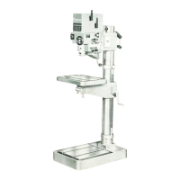
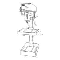
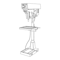
NO. 24503 DRILL PRESS
MECHANICAL PREPARATION
MOUNTING
To
assure
optimum accuracy and vibration
free operation, the
machine
should be leveled
on and mounted to a concrete
base.
The drilling table should be used as a
reference plane for level-
ing. A spirit level on this surface will
provide the required
accuracy.
Locate four concrete fasteners to
line up
with the mounting
holes in the machine base. Bolting
thru these holes into the
concrete fasteners will secure the
machine.
nhen
tightening
the securing bolts, the drilling table
should
be checked,
with a
spirit level, to assure that it
has remained level.
ASSEMBLING
1. Remove the top of the shipping container.
2. Remove the table brace
and lift the
table out of
the ship-
ping container.
3. Unbolt the base from
the shipping container and
lift it
out.
4. Remove
the four hex head bolts
from the base.
one of
these bolts holds
the table raising
handle.
5. Remove
the two bolts
holding
the
base of the
column
to the
end of the shipping
container.
6. Remove the two
supports
above
the
head.
7. Remove
the wedge
between the
feed
lever and
side of
the shipping
container.
8.
Remove
the
brace over
the
spindle.
9.
Remove
from
the
shipping
container
one plastic
parts
bag
and
a
package
containing
the
head raising
crank.
NOTE:
The
column
assembly
weighs over
300
pounds
and
must
be
handled
carefully
to avoid
dropping,
bending or break-
ing
any
part
on
the
assembly.
Therefore
in removing
this
assembly
from
the
container
an
over
head
hoist or
the required
manpower
must
be
available.
10. Lift
the
column
assembly
out
of the
container and place
it
vertically
over
the
base.
11. Bolt
the
column
to
the base
with the
four
hex head bolts
removed
in step
12. Line
up
the
set
screw
in
the
table
raising
handle so that
It
is
perpendicular
to
the
flat
on the
table
raising
shaft.
13.
Push
the
handle
on
to the
shaft
until
the
hub and
the end
of
the
shaft
are
even.
14.
Tighten
the
set
screw.
The
required
allen wrenches are
supplied
in the
plastic
parts
bag.
15. Screw
the
two
largest
plastic
balls
onto the threaded ends
of
the
feed lever.
16. Unlock
the
table-column
lock and rotate the
table arm
900
about the
column.
17. Loosen
the table lock
by rotating
the lever
clock-wise.
18. Place the stem on the
bottom of the work table
into the
bore in the table arm with the smaller offset towards the
column.
19. Push
the
table all the
way down so that the shoulder
on
the
stem is resting
on the
arm.
20. Straighten
the table
with
respect to
the arm and lock it
by
rotating the locking lever
counter-clockwise.
21.
22.
23.
24.
25.
26.
Rotate the table arm assembly
back
under
the
headed
lock
it with the table-column locking lever.
Unlock the head-column lock and lift the
head
up
until
the gear
teeth can
be seen thru
the bore
for the
raising
crank.
Lock the head-column lock.
Insert the shaft of the head
raising crank into its bore
in the head, rotating it slightly
to allow the
pinion to
line up with the rack on the
column and push
it in ali
the way.
Adjust
the locking screw so that
it holds the
assembly
in
while
not restricting its radial motion.
Lock the locking screw with the nut provided.
CLEANING
Clean the machine
thoroughly removing
all of the shipping
preservative with
gasoline or other
suitable
solvent.
LUBRICATING
All
ball
bearings and
gears in the machine
have been
greæed
at
the
factory.
When
lubricating through
the oil nipples
which are
placed
on
the machine
only first
class
machine oil
should be
used
and
only a few
drops each time.
Too ample
might
damage the motor
which is
placed in
the spindle housing.
Level
plug (A) for the
oil level in the
feed gear box is
placed at
the
rear
on the cover.
Fill the power feed gear
box to the level
plug (A) (see 7)
with Shell Spirex, 80 EP, or equivalent
oil. Use no more than
three drops of
oil.
Coat the
column, the
table, and the baw with a light coating
of
machine oil.
Coat the table raising
gear rack with
a light layer of Shell
Alvina
EP2 or Shell Dorina EP2
grease.
ELECTRICAL
PREPARATION
ELECTRICAL
REQUIREMENTS
This
machine
requires
a
fused, 3
phase.
60
cycle
power
soure
of the
voltage
specified
on
the
nameplate
±
10%,
since
it
is
not a dual voltage
unit.
Before
connecting
the machine
to
the
power
source
make
certain
the
nameplate
voltage
and
the
voltage
of the
power
source
match.
A separate
110 volt
single
phase
line
is
also required
for
work table
light.
FUSING
Fuses
for
the power
source
can be
selected
using
the
follow
ir
v
table.
Voltage
Fuse
Type
220
Standard
Delay
Standard
Delay
15
8
8
4
 Loading...