ELECTRICAL
CONNECTIONS
MOTOR
1.
Remove
the
four slotted screws
at
the corners
of the
thermal•overload,
and the
thermal overload.
2. Pull
the
three
short wires that
run
between the thermal
O
overload
and
the
connector, on
the left
and to the reår
of
the
head,
out of the
connectors.
3.
Run a
four
wire
flexible
conduit or
a four wire soft cord
to
that
connector.
4.
Remove the
three
wires
on the top
of the overload and
replace
them with the
three power
lines 'rom the supply.
5. Connect the grounding
line to the
terminat on the over-
load with the
green and
yellow striped wire.
6. Replace the overload
and the
four slotted screws.
7. Push the black
button on the
overload switch in.
8. Turn on the power
source.
9. Turn the speed
selector
to I with a non-reversing switch,
to to I clockwise
with a reversing switch.
10. Check
the spindle
rotation. If the spindle rotates
clock-
wise the electrical
connections are correct. If the spindle
rotates counter clockwise go to step
Il Remove the overload and interchange any two of the
three power leads.
12. Replace the overload and the four slotted
screws.
SPEED SELECTOR
TCH
M
13
WHITE
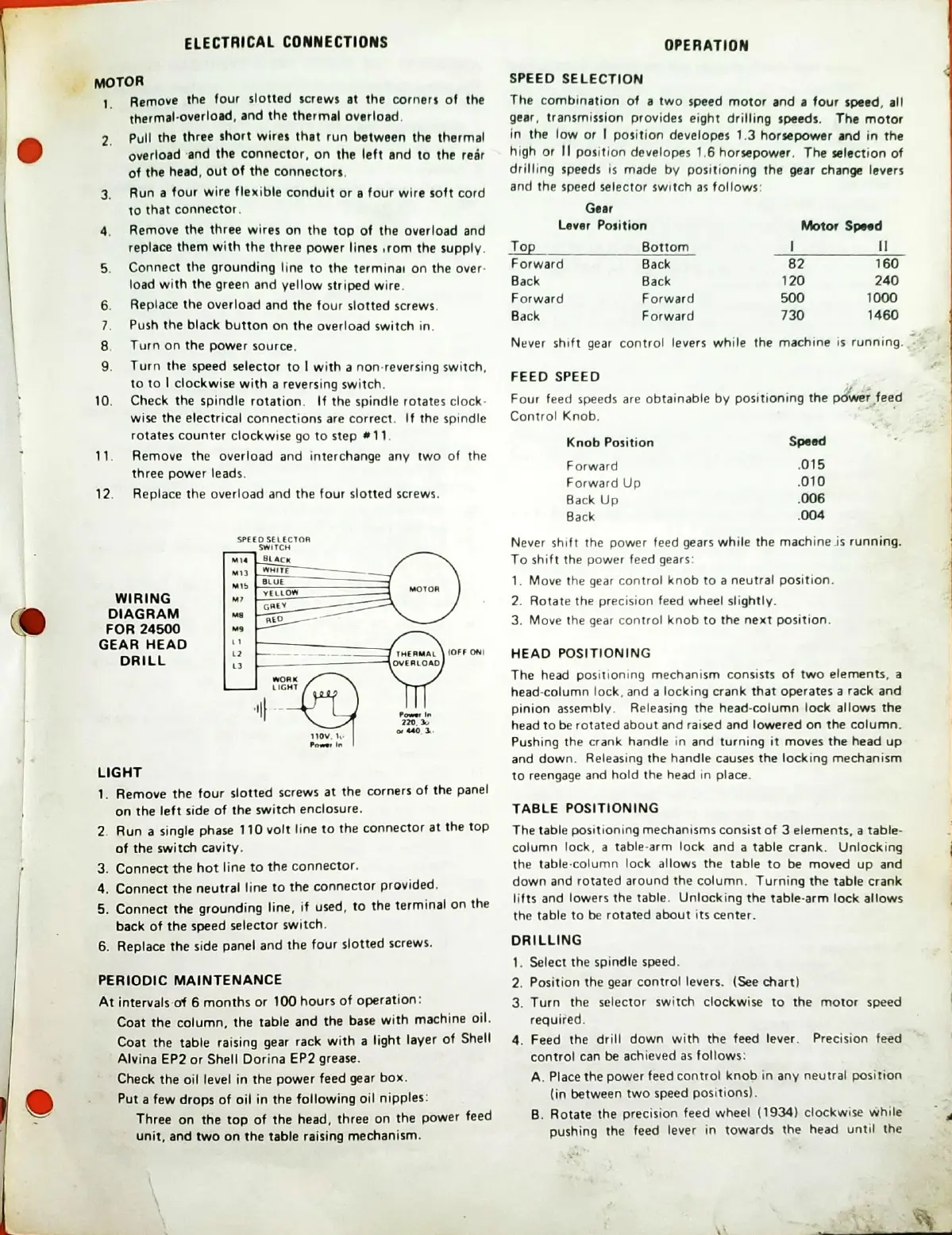
WIRING
YELLOW
GREY
DIAGRAM
FOR 24500
GEAR
HEAD
THERMAL
(OFF
DRILL
OVERLOAD
WORK
L
IGHT
220.
Itov.
LIGHT
I. Remove
the four
slotted
screws
at the
corners
of
the
panel
on the
left side
of the
switch
enclosure.
2 Run a
single phase
110
volt
line
to the
connector
at
the
top
of
the switch
cavity.
3. Connect
the
hot
line
to the
connector.
4. Connect the
neutral
line
to
the
connector
provided,
5. Connect
the
grounding
line,
if
used,
to
the
terminal
on
the
back of the
speed
selector
switch.
6. Replace
the side
panel and
the
four
slotted
screws.
PERIODIC MAINTENANCE
At intervalsof 6
months or
100
hours of
operation:
Coat the column,
the table
and
the base
with
machine
oil.
Coat the
table
raising gear
rack
with
a
light
layer
of
Shell
Alvina
EP2 or
Shell Dorina
EP2
grease.
Check the
oil level
in the power
feed
gear
box.
o
Put a
few drops of oil in the
following
oil nipples:
Three
on the top of
the head,
three
on the
power
feed
unit,
and two on the table
raising
mechanism.
OPERATION
SPEED
SELECTION
The
combination
of a
two speed motor
and a four
speed, all
gear,
transmission provides
eight drilling
speeds. The
motor
in the
low or I position
developes 1.3
horsepower and in the
high
or Il
position developes 1.6
horsepower. The
Election of
drilling
speeds is made
by positioning the gear change
levers
and
the speed selector switch as
follows:
Gear
Lever Position
%tor Sped
Top
Forward
Back
Forward
Back
Bottom
Back
Back
Forward
Forward
82
120
500
730
160
240
1000
Never shift gear control
levers while
the machine is
running.
FEED
SPEED
Four
feed speeds are obtainable
by positioning
the p;wer feed
Control Knob.
Knob Position
Forward
Forward Up
Back Up
Back
Speed
.015
.010
Never shift the power
feed gears while
the machine -is
running.
To shift the power
feed gears:
I. Move the gear
control knob to a neutral position.
2. Rotate the precision feed
wheel slightly.
3. Move the gear
control knob to the next position.
HEAD
POSITIONING
The head
positioning mechanism consists
of two elements, a
head-column
lock, and a locking crank that operates a
rack and
pinion
assembly. Releasing the
head-column lock allows the
head
to be
rotated about and raised and lowered on the
column.
Pushing
the crank handle in and turning
it moves the head up
and
down.
Releasing the handle causes the locking mechanism
to
reengage and hold the head in place.
TABLE POSITIONING
The table positioning
mechanisms consist
of 3 elements, a table-
column
lock,
a table-arm lock and a
table crank. Unlocking
the
table-column
lock allows the table
to be moved
up and
down
and
rotated around the column.
Turning the table crank
lifts and
lowers the table.
Unlocking the
table-arm lock
allows
the table to be
rotated
about its
center.
DRILLING
l.
2.
3.
4.
Select the
spindle
speed.
Position
the gear control levers. (See chart)
Turn
the
selector switch clockwise
to the motor speed
requited.
Feed
the
drill down
with the feed lever. Precision feed
control
can
be achieved
as follows:
A.
Place the
power
feed
control knob in any neutral position
(in between
two speed
positions).
B.
Rotate
the
precision
feed wheel
(1934) clockwise
While
pushing
the
feed
lever in towards
the head
until the
 Loading...