Page 8 of 12
Document No.: IM TMA227-15
Revision: A
TMM PUSH HANDLE
FIELD INSTALLATION AND USAGE INSTRUCTIONS
INSTALLING THE NEW PUSH HANDLE ASSEMBLY (CONTINUED)
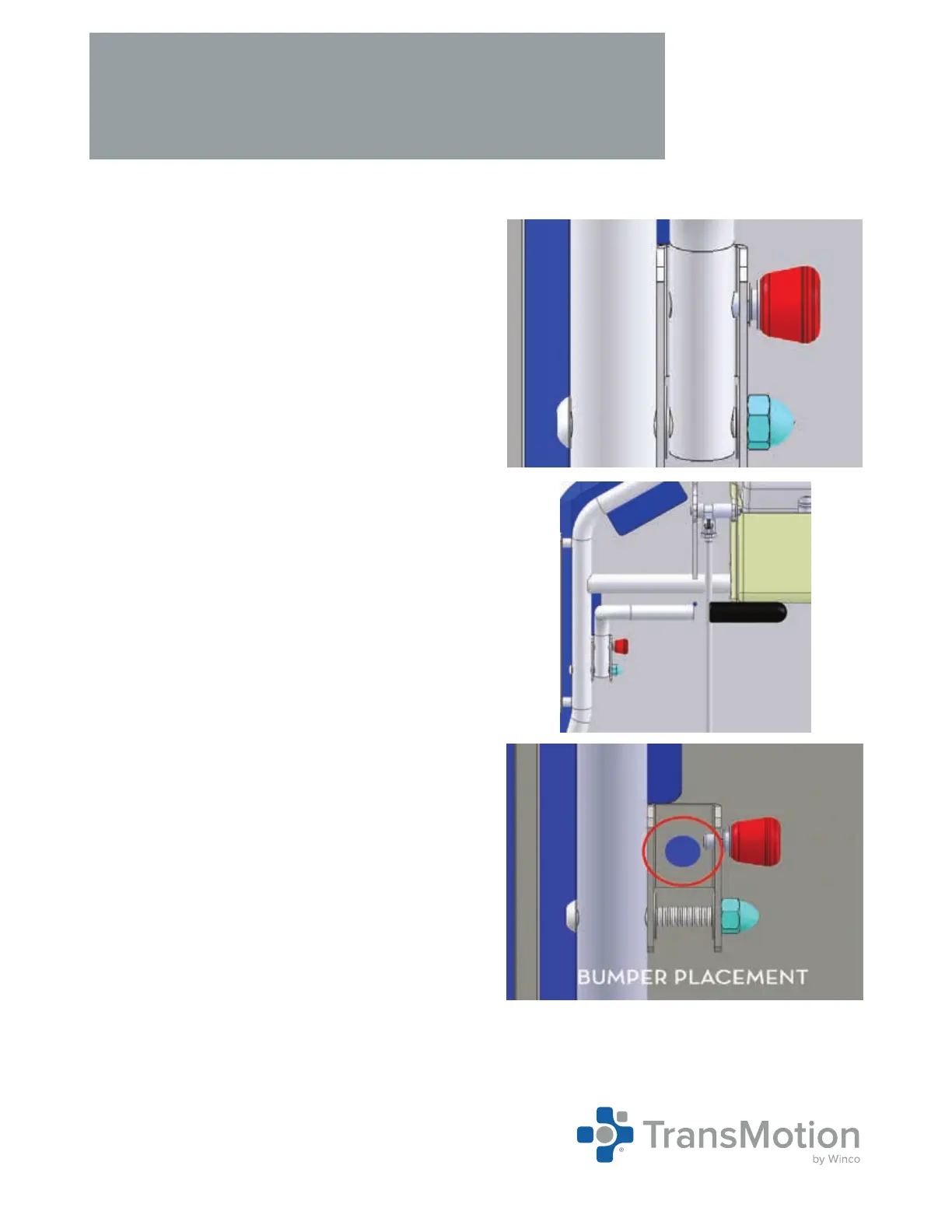
2. Securley tighten the cap nut onto the bolt using the
3/8” allen wrench and 1/2” socket wrench (Fig. 3).
3. Slide one (1) push bar grip onto the push handle
assembly (Fig. 4).
4. If the device does not already have one installed,
add one (1) adhesive backed bumper to the back of
the device as shown (Fig. 5). If the device already
has one installed, you may remove the old one and
replace it with a new one if necessary.
5. Repeat this entire process on the opposite side of
the device.
←
Fig. 3
Cap Nut
Fig. 4
←
 Loading...