WindSonic Doc No 1405 PS 0019 Issue 25 February 2017
22
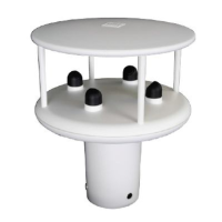
7.8 Connecting to a PC using RS422 (Option 2 or 3)
WindSonic
9 Way circular connector
PC with RS422/232
converter
Signal names Pin nos. Cable – 4 twisted pairs Signal names
TXD+
TXD –
4
5
RXD +
RXD –
RXD+
RXD –
6
7
TXD +
TXD –
Signal Ground
1
Signal Ground
Do NOT connect
at this end
N/A Screen and drain wires
Chassis ground
V supply +
V supply -
2
3
+
–
DC Power
supply
(See Para 7.3.2)
Notes
WindSonic to be set for RS422/RS485 mode (E2, default).
Analogue Outputs are also simultaneously available from the Option 3 unit.
Default Settings
The WindSonic Option 2 and 3 unit is factory configured with the following default
settings:
M2, U1, O1, L1, P1, B3, H1, NQ, F1, E2, T1, S4, C2, G0, K50
See Section 10 Configuring for further details
WindSonic Doc No 1405 PS 0019 Issue 25 February 2017
23
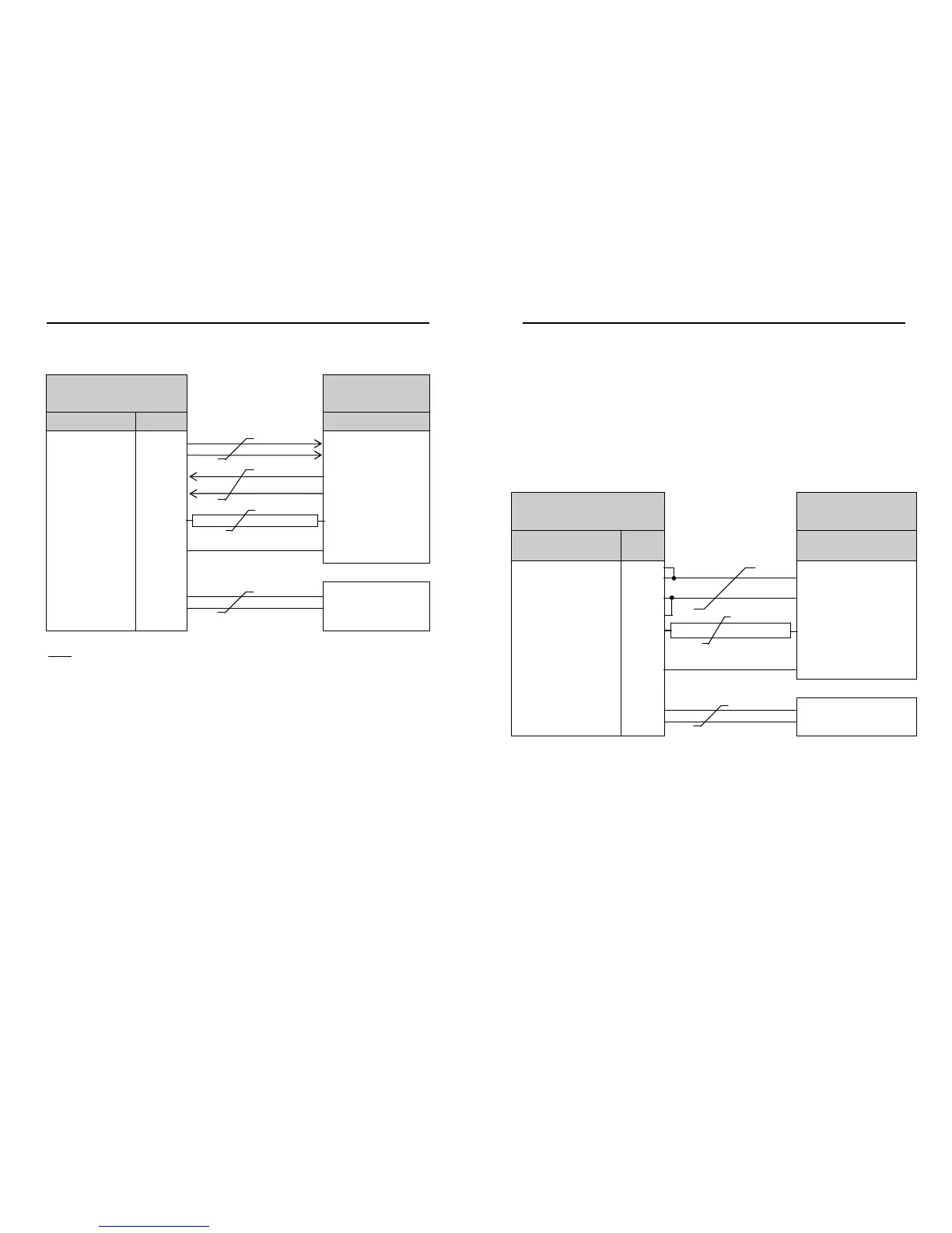
7.9 Using RS485 (2 wire point to point) with Option 2 or 3
units
Notes
1. The unit must be set for RS422/485 mode (E2 setting).
2. WindSonics must be set in Polled mode, a node address letter may be given if
required.
See Section 9.1 WindSonic node address.
3. Customers may poll using terminal software (NOT supplied).
4. As unit is point to point only it cannot be networked with other RS485 2 wire devices.
WindSonic
9 Way circular connector
PC with RS485 card
Signal names
Pin
nos.
Cable – 3 twisted pairs Signal names
TXD+
RXD+
4
6
T/RXD +
TXD –
RXD –
5
7
T/RXD –
Signal Ground
1
Signal Ground
Do NOT connect
at this end
N/A Screen and drain wires
Chassis ground
V supply +
V supply -
2
3
+
–
DC Power supply
(See Para 7.3.2)
NOTE:
Analogue Outputs are also simultaneously available from the Option 3 unit.