WindSonic Doc No 1405 PS 0019 Issue 25 February 2017
56
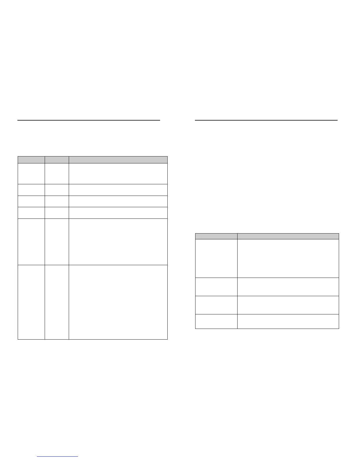
10.8 Configuration / Diagnostic Information
Each of these commands causes a response from the WindSonic.
Item Command Response
Type
and serial No.
D1
Y16120001
Software
version
D2 2368-110-01
Unit
configuration
D3 M2,U1,O1,L1,P1,B3,H1,NQ,F1,E2,T1,S4,C2,G0,K50,
Supply
Voltage
D5 +11.7v
Self-test
D6
See Section 12.2 Self-Test (Still Air)
CHECKSUM ROM:AB7D AB7D *PASS*
CHECKSUM FAC:04F4 04F4 *PASS*
CHECKSUM ENG:082A 082A *PASS*
CHECKSUM CAL:A9C1 A9C1 *PASS*
Hardware
Configuration
D10
Serial Number : Y16120001
Software Version : 2368-110-01
Class : WINDSONIC (Gill Instruments Ltd)
Number of axes on this unit : 2
Axes tilted 45deg to horizontal plane
Analogue outputs: 2 (12bit)
Analogue output modes: 0-5V 4-20mA 0-20mA
Maximum output rate: 004Hz
Maximum base rate on this unit is 16Hz sampling
Available baud rates: 002400 004800 009600 019200 038400
Available messages: M1 M2 M3 M4 M5 M12 M14 M15
M16
Safe mode enabled
Parity control allowed: F1 F2 F3
Communication modes: RS232 RS485/422
WindSonic Doc No 1405 PS 0019 Issue 25 February 2017
57
11 MAINTENANCE & FAULT-FINDING
11.1 Cleaning
If there is any build-up of deposit on the unit, it should be gently cleaned with a cloth
moistened with soft detergent. Solvents should not be used, and care should be taken to
avoid scratching any surfaces. The unit must be allowed to defrost naturally after being
exposed to snow or icy conditions, do NOT attempt to remove ice or snow with a tool.
Do NOT remove black “rubber” transducer caps.
11.2 Servicing
There are no moving parts or user-serviceable parts requiring routine maintenance.
Opening the unit or breaking the security seal will void the warranty and the calibration.
In the event of failure, prior to returning the unit to your authorised Gill distributor, it is
recommended that:
1. All cables and connectors are checked for continuity, bad contacts, corrosion etc.
2. A bench test is carried out as described in Section 12.1.
3. You contact your supplier for advice
11.3 Fault Finding
No output
Check DC power to WindSonic, cable and connections.
Check comms settings of WindSonic and host system match,
including correct Com port
Check unit is in Continuous mode
Check that in-line communication devices are wired correctly.
NOTE: It is usual for Anemometer TX + to be connected to
converter device RX +
Corrupted output
Check comms settings of WindSonic and host system match.
Try a slower baud rate.
Check cable lengths and type of cable.
One way
communication
Check WindSonic and host system are both set to the same
protocol RS232, RS422, or RS485.
Check wiring is in accordance with the manual.
Failed / Incorrect
WindSonic output, data
invalid flag
Check that transducer path is not blocked