© 2004 Wohler Technologies Inc. ALL rights reserved
12
AMP2-DA/AVU and AMP2-DA/APP User Manual P/N 821584 Rev-A
TERM 2
Note: Section 3 of DIP module is not functional
TERM 2
AES Input 1 Termination
Unterminated
x
TERM 1
ERROR
TERM 1
ERROR
x
Terminated
TERM 1
ERROR
TERM 2
x
AES Input 2 Termination
TERM 2
x
TERM 1
ERROR
2
2 44
TerminatedUnterminated
AES Error Indication Settings
Note: Section 3 of DIP module is non-functional
Error/Fault Type = Red LED
Reception
Error (Only)
Reception and
Data Error
1 1
ERROR
TERM 1
TERM 2
x
ERROR
TERM 2
TERM 1
x
D
A
B
C
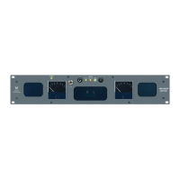
Please refer to Figure-2b on the facing page to familiarize yourself with the rear panel features of the AMP2-DA/AVU and AMP2-DA/
APP unit. The following sections describe these features and are referenced, by letter, to Figure-2b.
Rear Panel Features
Section 2: Operation
Power Connector
Attach a standard IEC-320 power cord between this connector and mains power (100 - 250VAC, 50/60 Hz). The front panel
Power LED (Item 8, page 8) will glow GREEN to indicate operating voltages are present.
AES Input Termination and Error Indication Type DIP Switch
This 4-position DIP switch module is used to set the termination characteristics for the AES inputs and to set the error type
indicated by the AES Status LED (Item 5, page 8). Note: Section 3 of the DIP module is not used.
AES Input Termination:
In the event that either of the two AES input channels is fed to downstream equipment, the associated DIP switch section
(section 1 = IN 1 and section 3 = IN 2) must be placed in the UP (Unterminated) position. If there is no downstream
equipment connected, then the associated DIP switch section must be placed in the DOWN (Terminated) position.
See below left for a diagram of termination settings.
Error Indication Type:
DIP switch section 1 may be set to allow the AES Status LED to indicate either reception and data errors or to indicate
reception errors only. See the diagram below right for settings.
AES Unbalanced BNC Input Connectors (IN 1 and IN 2)
These two AES inputs on female BNC connectors (IN 1 and IN 2) are meant to receive standard AES signals and are
configured for unbalanced, 75 Ω connections. Either of the two inputs is selected by setting the AES Source Select
Switch (Item 4, page 8) on the front panel to 1 or 2. Note that the unit will monitor the selected AES source only when the
Analog/Digital Source Select Switch (Item 3, page 8) is set to DIGITAL.
Optional balanced inputs on female XLR connectors may be specified for the AES inputs in lieu of BNC connectors.
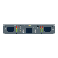
AES Input Level Gain Calibration DIP Switch
Input Level Gain Calibration, the analog level which corresponds to a given digital input value, is settable via this DIP
switch. The factory setting is +4 dB (analog) = -20 dBFS (digital). See the silk-screened chart on the rear panel or the
diagram below for settings.
(Continued)