Dealer Service 26
MAN1256 (3/23/2018)
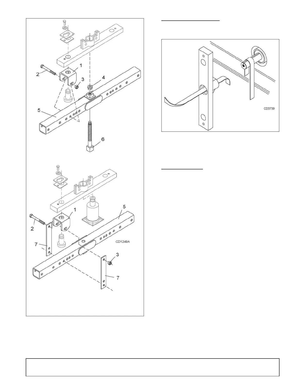
Figure 24.
Crossbar Removal
CROSSBAR INSTALLATION
1.
Using emery cloth (220 or finer), remove surface rust, and foreign
material from hub, splined gearbox vertical shaft, and crossbar. See
Figure 25.
Figure 25.
Example of Crossbar and Gearbox Shaft
2.
Install crossbar (5) on splined shaft. Install washer (18), castle nut (19),
and cotter pin (20). Torque nut to 610 N-m (450 lbs-ft).
3.
Install blades, reinstall them using existing hardware.
Torque cap screws
to 115 N-m (85 lbs-ft).
CROSSBAR TIMING
Crossbar must be re-timed anytime a crossbar or a side drive is disconnected.
1.
To re-time crossbars, position bars as shown in Figure 26.
2.
The right crossbar will be at right angles to the front of the cutter.
3.
Measure from the front of the cutter to the blade pin on each side
crossbar.
4.
Hold crossbars in position while connecting the side drivelines.
1. Clevis
2. 5/8 NC x 4 Cap screw
3. 5/8 NC Hex nut
4. Pad assembly
5. Tube assembly
6. Screw assembly
7. Puller link



 To Next Page