28 Assembly
MAN0476 (Rev. 2/10/2006)
DRIVELINE & SHIELD INSTALLATION
Select either the standard shear bolt or optional slip
clutch driveline.
Shear Bolt Driveline Installation
IMPORTANT
■ A grade 2 bolt must be used for the shear bolt
to provide gearbox protection.
NOTE: It maybe necessary to clean or deburr the gear-
box input shaft and or driveline yoke with emery cloth
or file before installing.
1. Position shield (7) against gearbox. Secure using
cap screw (8), lock washers (9), and flat washers
(10). Torque hardware to 12 lbs-ft.
2. To prevent seal damage, carefully push driveline
onto gearbox input shaft until it contacts the
gearbox housing.
3. Place retaining ring (6) in slot on input shaft and
snap into place.
4. Align the holes in the driveline yoke and gearbox
input shaft. Install and tighten shear bolt (4) and
nut (3).
5. Install rear drive shield to driveline.
6. Lubricate rear driveline half and install front
driveline half.
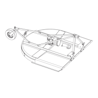
Figure 23. Shear Bolt Driveline Assembly
Slip Clutch Driveline Installation (Optional)
IMPORTANT
■ A grade 8 bolt must be used to attach clutch
driveline to gearbox.
A new slip clutch, or one that has been in storage over
the winter, may seize.
NOTE: It maybe necessary to clean or deburr the gear-
box input shaft and or driveline yoke with emery cloth
or file before installing.
1. Before operating slip clutch, make sure it will slip.
Refer to Driveline Slip Clutch Adjustment, page
17.
2. Position shield (3) against gearbox. Secure using
cap screw (4), lock washers (5), and flat washers
(6). Torque hardware to 12 lbs-ft.
3. Slide driveline (7) onto gearbox input shaft, align
holes between driveline yoke and gearbox input
shaft and secure with bolt (1) and nut (2).
4. Lubricate rear driveline half and install front
driveline half.
Figure 24. Optional Slip Clutch Driveline Assembly
1. Driveline shield
2. Input shaft (slot)
3. 1/2 NC Lock nut
4. 1/2 NC x 3 Cap screw GR2 (Shear Bolt)
5. Gearbox
6. Retaining ring
7. Shield
8. M8 x 1.25P x 20 mm Cap screw
9. 5/16 Lock washer
10. 5/16 Flat washer
1. 1/2 NC x 2-3/4 Cap screw GR8
2. 1/2 Lock nut
3. Shield
4. M8 x 1.25 x 20 mm Cap screw
5. 5/16 Lock washer
6. 5/16 Flat washer
7. Driveline