Operation 15
MAN0988 (11/5/2012)
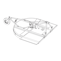
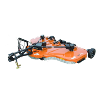
Figure 13. Precision Super Seeder above Wooden
Blocks
6. Lower seeder to resting position on wooden blocks
for support during front roller adjustment. (Follow
tractor safe parking procedure in tractor operator’s
manual).
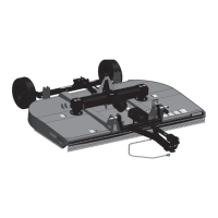
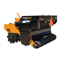
7. Raise the adjustment handle and pivot it to the next
adjustment hole (see Figure 15). Move handle
rearward; front rollers will start to angle forward.
Continue this process until front rollers have the
desired angle and holes align between frame rail
and roller side weldment.
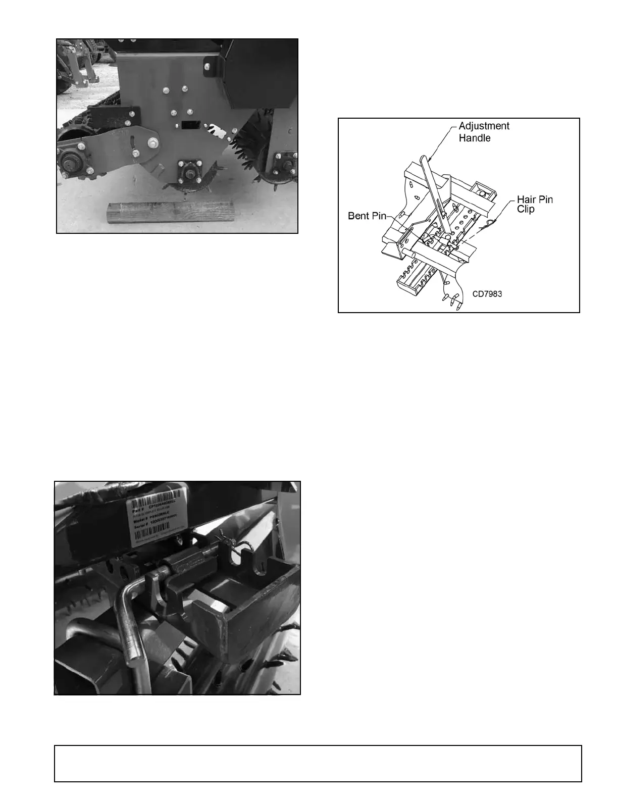
8. Partially engage bent pin to hold adjusted position.
9. Lift seeder and pull forward to clear wooden
blocks. Lower seeder to rest position on the
ground/level surface, and fully install bent pin and
hair pin clip (see Figure 14).
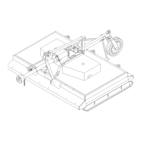
Figure 14. Bent Pin Installation
10. Reverse this procedure to move front roller back
into straight position.
NOTICE: The 72" and 84" seeders use the front
notch of the frame rail for the maximum roller angle
(19° and 17° respectively). The 60" seeder uses
the 2nd notch from the front for the maximum roller
angle (20°). The 48" seeder uses the 3rd notch
from the front for the maximum roller angle (20°).
Figure 15. Spike Roller Handle Adjustment (mast
plate hidden for picture clarity)
Adjust Front Disc Angle
1. Position tractor and Precision Super Seeder on a
level surface.
2. Set seeder on the ground and set parking brake.
3. Remove bent pin and hair pin clip from front of
seeder (see Figure 12).
4. Place wooden blocks (minimum 4" thickness) on
ground to align with each end of the Precision
Super Seeder.
5. Raise seeder slightly off the ground and position
seeder over wooden blocks by moving tractor. Do
not allow wooden block to contact the front disc
gang (see Figure 13.)
6. Lower seeder to resting position on wooden blocks
for support during front disc adjustment. (Follow
tractor safe parking procedure in tractor operator’s
manual.)
7. Raise the adjustment handle and pivot it to the next
adjustment role (see Figure 15). Move handle
forward; front discs will start to angle rearward.
Continue this process until front discs have the
desired angle and holes align between from rail
and disc slide weldment.
8. Partially engage bent pin to hold adjusted position.
9. Lift seeder and pull forward to clear wooden
blocks. Lower seeder to rest position on the
ground/level surface, and fully install bent pin and
hair pin clip (see Figure 14).
(Rev. 7/12/2019)
 Loading...