11
PN 55191 (4/22/99)
Spacers Required
Under Caster Arm Pivot Tube
Cutting 1/2” 3/4” 1” 1 -1/4”
Height Spacer Spacer Spacer Spring
1-1/2”
2” 1
2-1/2” 1
3” 11
3-1/2” 2
4” 12
4-1/2” 111
5” 1111
5-1/2” 121
6” 1121
CUTTING HEIGHT CHART
Remember, measurement at location “A” should not
be less than location “B” and should not be over 1/2”
greater than location “B”
Tractor Top Link Adjustment
(Figure 4 & Figure 5)
Adjust tractor top link so mower is level at 16”
between caster wheel and ground (dimension C,
Figure 4). This will allow the mower to follow ground
contour.
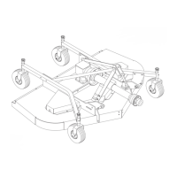
Front Caster Wheel Interference Check
(Figure 4)
IMPORTANT
J Donot operatetractorand moweruntil
this interference check has been per-
formed. If you change tractors, you must
perform the check for that mounting.
Perform this check with all of the spacers and springs
above the caster wheel arm. This will place the caster
wheels in their highest position and provide the lowest
cutting height for the mower.
Raise mower with tractor hydraulics to 16” at
dimension “C” or maximum height of tractor lift,
whichever is less.
Pivot both front caster wheels forward and check that
there is clearance between caster wheels and tractor
tires. If there is interference, you must not use front
caster wheels on the mower with this tractor .
Optional check chains are available and may be used
to control front deck height.
“C”
CD3528C
Figure 4. Front Gauge Wheel Interference Check
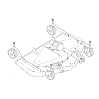
Optional Check Chain Attachment
(Figure 5)
Attach check chain brackets (3) and the tractor top
link (1) to tractor top link attachment point with cap
screw (7) and hex locknut (8) as shown. Always
maintain the same number of links on each chain.
Connect rear end of tractor top link (1) to mower’ s
floating top link (9) with high-strength clevis pin and
retaining pin supplied with top link.
Top link adjustment will be required when cutting
height is set.