20
PN 55191 (4/22/99)
IMPORTANT
J Pulley installation sequence is very
important for bearing life. Follow the
sequence exactly.
Install pulley and split taper bushing with integral key
on spindle shaft. Install cap screw and flat washer in
top of spindle shaft. Torque this cap screw to 12
lbs.-ft., then alternately tighten split taper bushing cap
screws to 12 lbs.-ft.
GEARBOX MAINTENANCE
Read all of this section before starting any repair.
Many steps are dependent on each other .
Check gearbox for leakage and shaft side and end
play. If excessiveshaft play is found, disassemblebox
and inspect bearings and shafts.
Leakage can occur at top cover and at shaft seals.
Leakage problems should be corrected immediately
to prevent damage to drive belt from gearbox oil.
Always clean any spilled lubricant with a cloth
moistened with a non-flammable, non-toxic degreas-
ing agent or commercial detergent and water . Be sure
to clean pulley grooves.
The sealants recommended for gearbox repair are
Permatex Aviation 3D Form-A-Gasket
or Loctite
515 Gasket Eliminator .
Leakage Repair
To repair top cover leakage, clean top cover and
housing sides, then remove cover. Remove old
sealant from cover and housing.
Apply sealant to top cover and replace. Reinstall cap
screws in top cover and torque to 38 lbs.-ft.
Horizontal seal leakage should be repaired by
replacing the seal. The gearbox should be removed
from the mower to accomplish this. Remove old seal
with care to prevent damage to seal bore and shaft.
Sealant should be applied to the seal bore before
installing the new seal. The new seal should be
seated squarely in the bore against snap ring. Press
seal into place with a piece of pipe or tubing that sets
against the outside edge of the seal. Tubing with an
outside diameter which is too small will bow seal cage
and ruin the seal.
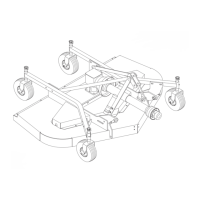
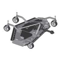
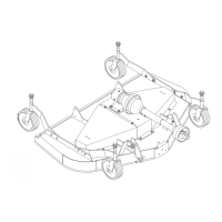
Removing Gearbox from Mower
Remove belt and driveline shields.
Remove rear driveline shield retainers and pull shield
ahead to gain access to front of gearbox. Remove
snap ring from gearbox shaft. Remove shear bolt
from end yoke and remove driveline.
Permatex Aviation 3D Form-A-Gasket is a registered trademark
of the Permatex Corporation.
Loctite is a registered trademark of the Loctite Corporation.
Remove drive belt from drive sheave.
Remove gear stand from mower.
Remove drive sheave from mower by removing cap
screws from split taper bushing and turning them into
threaded holes on bushing flange. Tighten evenly,
forcing the bushing and drive sheave apart.
Remove gearbox from gear stand.
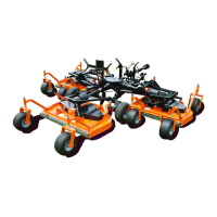
Gearbox Disassembly (Figure 12)
A five ton press will be required for vertical gear shaft
removal.
WOODS puller kit (PN--19077) is required to remove
the horizontal shaft from the gearbox.
Remove top cover (14) and drain all gear lube.
Clamp gearbox upside-down in a large vise. Place
driveline on the horizontal shaft to prevent shaft
rotation. Remove stake nut (23). If nut is too tight to
remove with a spanner wrench, loosen with punch
and hammer.
Carefully remove vertical shaft seal (21) to prevent
damage to shaft threads and seal bore.
Remove PTO driveline and remove gearbox from
vise. Use care when removing horizontal shaft seal
(1) and retaining ring (2) to prevent damage to shaft
seal surface and housing bore.
Secure input gear (8) against housing with a “C”
clamp. Place puller plate (30) over horizontal shaft
(6). Assemble puller halves together as shown in
Figure 12 using bolt (28 and nut (29). Puller flanges
must engage locking groove in horizontal shaft.
T ighten puller bolts evenly to remove shaft from
housing.
Place housing upside-down in a press and remove
vertical shaft (15) by pressing through top of housing.
Remove bearing cone (16) from vertical shaft (15)
with a spreader. Remove all cups from housing with a
puller or by carefully driving them out with a punch.
Inspect gears for excessive wear. Gears are forged
and surfaces will appear rough, even when new.
Some wear is normal. Gears will show more wear on
the loaded side and the pattern should be smooth.
Inspect both gear shafts and stake nut for grooves,
nicks, or bumps where the seals seat. Replace if
damage cannot be repaired by resurfacing with
emery cloth.
Clean gearbox housing and inspect for damage.
Replace if cracks are found.
Gearbox Assembly (Figure 12)
Press cups (10, 17 & 19) into housing until they seat
tightly against machined shoulders. Press bearing
cone (16) onto vertical gear shaft (15) and seat it
against gear.