19
PN 55191 (4/22/99)
10
1
5
2
8
4
6
9B
9A
7
6
4
3
2
SEAL LIP
SEAL LIP
CD3534B
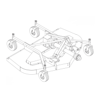
1. Spindle assembly
2. Seal
3. Sleeve
4. Bearing cone
5. Housing & cups
6. Cup
7. Shaft
8. 1/8 PTF 45° Grease fitting
9A. Grease fitting for right and center spindles
9B. 30° Grease fitting for left spindle
10. 1
8F x 1
8M PTF 45° Grease
ittin
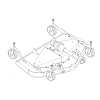
1. Spindle assembly
2. Seal
3. Sleeve
4. Bearing cone
5. Housing & cups
6. Cup
7. Spindle shaft
8. 45° Grease fitting
9A. Grease fitting for center spindle
9B. 30° Grease fitting for right and left spindles
10. 45° Grease
ittin
10
9B
5
9A
7
6
4
8
2
1
6
4
3
2
SEAL LIP
SEAL LIP
CD3523D
RM550 RM660
Figure 11. Spindle Repair
Should you overtighten bearings, hold spindle hous-
ing and rap spindle shaft with a lead hammer to
loosen bearings. Readjust bearings until proper
setting is obtained.
IMPORTANT
J Improper positioning of seals can
cause seal failure.
Proper seal installation is important. An improperly
installed seal will leak and could cause bearing failure.
Pull the rubber portion of seal back and locate spring.
Apply a thin coat of lubricant to bottom seal (2) and
install with spring up toward center of housing.
Place bottom seal squarely on housing. Select a piece
of pipe or tubing with an OD that will set on outside
edge of seal. A tube that is too small will bow seal cage.
Carefully press seal into housing, preventing distor-
tion to metal seal cage. Seal should seat firmly and
squarely against machined shoulder in housing.
Make sure seal lip did not roll under . Distortion to seal
cage or damage to seal lip will cause seal to leak.
Damaged seals must be replaced.
Apply a thin coat of lubricant to top seal (2) and install
with spring up away from center of housing. Top seal
should be flush with top of housing.
Lubricate spindle with a lithium grease of #2 consis-
tency with a MOLY (molybdenum disulfide) additive.
Vent top seal with blunt edged tool, such as a letter
opener, while filling with grease. Rotate housing on
spindle shaft, checking for free movement.
Blade Spindle Installation
Insert spindle through bottom of mower deck and
secure with cap screws and lockwashers previously
removed. Be sure to position grease fittings toward
lubrication access areas. Reinstall grease fitting
extension after spindle is secured in place. Refer to
lubrication chart, page 15.