27
PN 55191 (4/22/99)
CD3538B
1
13
5
2
4
6
7
8
9
9
10
11
7
12
3
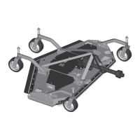
6. 1/2 NC x 2-1/4 Hex head cap screw GR5
7. 1/2” Lockwasher
8. Caster yoke and wheel
9. Height adjustment spacers
10. Spring
11. 1/2” 10 GA Flat washer
12. 1/2 NC x 1-1/4 Hex head cap screw GR5
13. Le
t belt shield
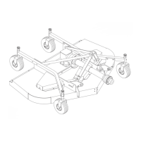
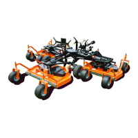
1. Frame rail
2. Frame lug
3. Caster arm
4. 1/2 NC x 1-3/4 Hex head
cap screw GR5
5. 1/2 NC Flanged hex locknut
Figure 21. Rear Caster Assembly
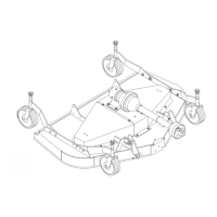
1. Driveline
2. QD Yoke
3. 5/16 NC x 3/4 Hex
head cap screw GR5
10
9
8
M5518
7
6
5
4
3
2
1
4. 5/16 Standard flat
washer
5. Counter-cone shield
6. Gearbox input shaf
7. Anti--rotation chain
8. Screw
9. Gearbox
10. 5
16 Lockwasher
Figure 22. Driveline Installation
Check Chain and Top Link Adjustment
(Figure 23)
Pivot up A-frame bars. Remove bolts from pivot link
and rear frame. Install offset link to the outside of
A-frame bars and inside of rear frame.
4
4
3
2
2
1
CD4303
1. Pivot link
2. Offset link
3. Rear frame
4. A-Frame bars
Figure 23. Check Chain & Top Link Adjustment