Assembly 43
MAN0943 (11/1/2013)
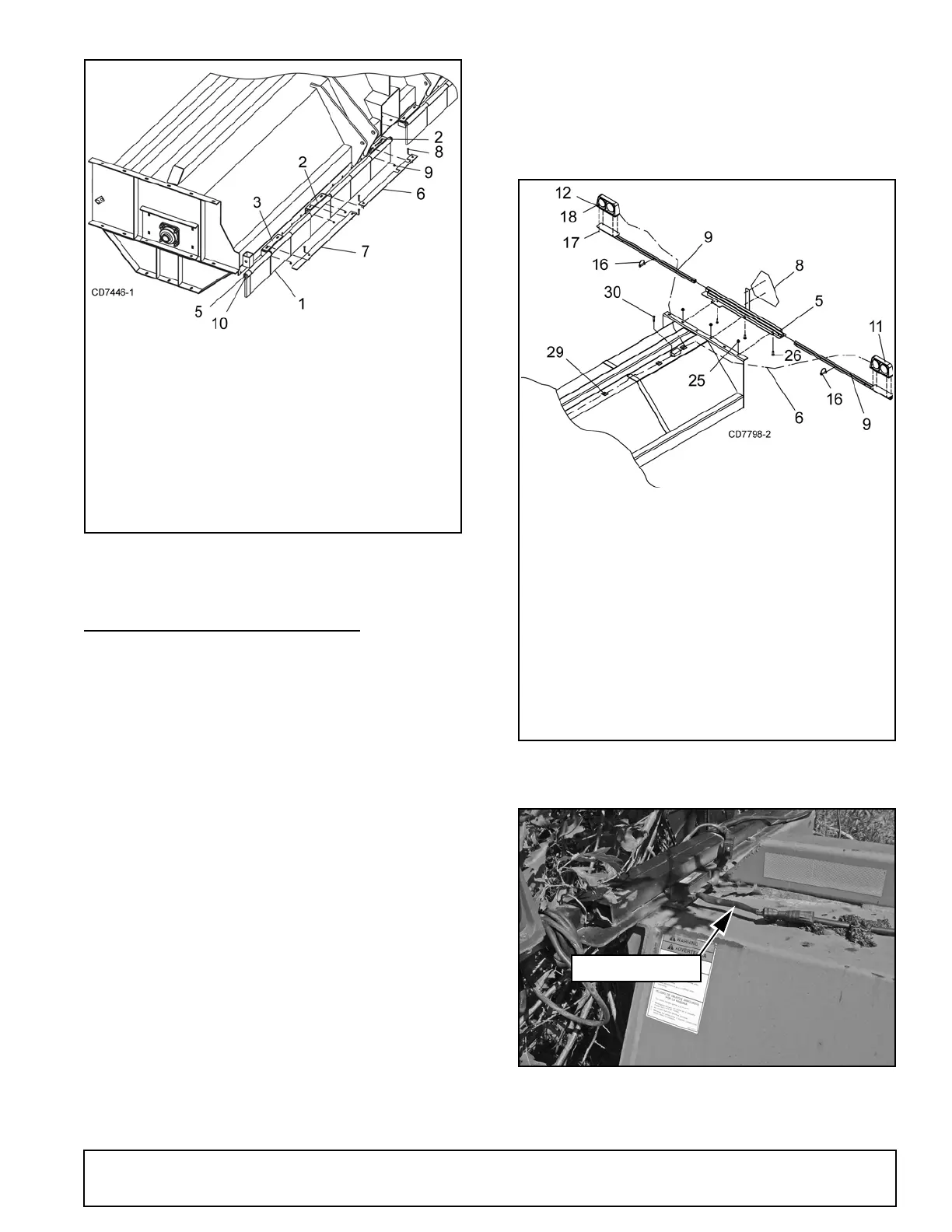
Figure 54. Rubber Flap Installation (15’ Shown)
SAFETY LIGHT INSTALLATION
1. Remove all components from shipping carton.
Make sure that all required hardware is included.
2. Attach dual safety lights (Figure 48) to safety light
mounting brackets (9) using cap screws (17) and
lock nuts (18).
NOTE: Make sure that light lenses are in the cor-
rect position in relation to direction of equipment
travel: amber lenses on the outside, red lenses on
the inside facing rear of shredder.
3. Install light bracket (5) on end of shredder using
cap screws (26) and lock nuts (25) on top of end
sheet.
4. Attach light mounting brackets (9) to light bracket
(5) using pins (16).
5. Secure SMV sign (8) to light bracket (5).
6. Plug ends of wiring harness into corresponding
plugs of the light units
NOTE: Left side of wishbone harness is labeled
“Left”.
7. Run wiring harness along top of shredder and
secure with enclosed adhesive-backed clamps
(29) approximately every two feet.
8. Secure wiring harness module to top of shredder
using self tapping screw (30).
9. Connect 7-pin connector of wiring harness to
tractor and test all light functions before actual use.
Figure 55. Safety Light Installed
Figure 56. Safety Light Wiring
1. Rubber flap
2. Flap bracket, right
3. Flap bracket, left
5. flap rod
6. Swing flap bar, mast plate
7. Swing flap bar
8. 3/8 NC x 1 Carriage bolt
9. 3/8 NC Flange lock nut
10.3/16 x 1-1/2 Cotter pin
5. Light Assembly Mounting Bracket
8. SMV Sign
9. Safety Light Mounting Bracket
11. Dual Lamp - Left Hand
12. Dual Lamp - Right Hand
16.Pin
17. 1/4 Flange Lock Nut
18. 1/4 NC x 1 HHCS
26. 1/2 NC x 1-1/2 Carriage Bolt
29. Adhesive backed clamps
30.5/16 NC x 3/4 Self Tap Screw