Manual 82006 Digital Reference Unit
Woodward 3
Chapter 2.
Installation and Adjustment
Introduction
This chapter includes information on unpacking, installation, setup, and checkout
of the Digital Reference Unit. Information on power requirements, location
considerations, and wiring information is also included.
Unpacking and Inspection
Before handling the unit, read page ii, Electrostatic Discharge Awareness.
Visually inspect the unit for damage such as bent or dented panels, and loose or
broken components. Immediately notify the shipper of any damage.
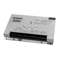
Compare the part number on the front panel with the chart on page 1 of this
manual to be sure the reference unit is compatible with the supply voltage to be
used.
CAUTION—BATTERY
To prevent damage to a direct-current powered control, make sure that the
alternator or other battery-charging device is turned off or disconnected
before disconnecting the battery from the control.
Location Considerations
The unit can be installed in any position that provides adequate ventilation and
space for servicing. Maximum power use is 3.0 W. The unit will generate a
minimal amount of heat during operation. The Digital Reference Unit will operate
between –40 and +185 °F (–40 to +85 °C). It is designed to withstand 4 Gs of
vibration between 5 and 500 Hz, and 60 Gs of shock.
The unit is not designed for mounting on the engine. Do not expose the box to
rain, or pressure wash.
The location should provide ready access to the terminals on the control which is
to be influenced by the unit.
See Figure 3-1 for installation dimensions.
Setting the Output Limits
The Low Limit potentiometer sets the minimum output from the Digital Reference
Unit. The Range potentiometer sets the maximum output at a position above the
Low Limit setting. Since the Low Limit setting changes the setting of the High
Limit (Range), it is necessary to always set the Low Limit first and to reset the
Range (High Limit) after any change in the Low Limit.
The following step-by-step procedure should be followed any time the limits are
set or reset.