DSS-2 Two-Channel Digital Speed Switch Manual 36598
2 Woodward
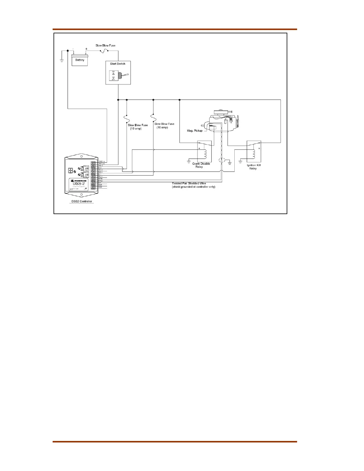
Figure 1. DSS-2 Engine Control System
How Speed Switches Work
The purpose of a speed switch is to monitor the speed of a rotating device, such as
an internal combustion engine, and close or open a set of switch contacts when
speed exceeds a threshold. Speed switches are most often used to disengage
starter motors when the engine starts, and to shut down the engine should an
overspeed occur. With the addition of some logic, speed switches may be applied to
a number of applications. Electrical loads controlled with a speed switch include
starter relays, ignition system power, indicator lamps, glow plug relays, solenoids
and electro-hydraulic valves.
Set vs. Reset
Speed switches make frequent use of the terms “Set” and “Reset.” The “Reset”
condition or state is that which exists when the unit is first powered up and when
engine speed is below the speed threshold. Once speed rises above the threshold
(set speed), the speed switch output (relay) transitions to the “Set” condition. In
some cases, depending on configuration, the speed switch can return to the “Reset”
condition when engine speed drops below a lower threshold (reset point), or when a
manual reset switch is actuated. The speed switch may also be configured to latch a
Set condition until battery power is cycled.
Normal vs. Reverse Relay Logic
A normally configured speed switch channel has the relay de-energized in the Reset
condition and energized in the Set condition. It is possible to configure each channel
in Reverse mode such that the relay is energized in the Reset condition and de-
energized in the Set condition. This is helpful in applications such as engine crank
disable where a loss of power to the DSS-2 should produce the same response as
 Loading...