Manual 36598 DSS-2 Two-Channel Digital Speed Switch
Woodward 3
exceeding the set engine speed. Configuring a channel in normal mode for a crank
disable feature could cause overcranking if power were interrupted to the DSS-2.
Autocrank
The DSS-2 speed switch channels can be easily configured to provide an autocrank
feature using the ACT. In this mode, applying battery voltage to the VER input will
initiate the starting sequence. When this happens, the relay will be energized until
either the engine starts, or a maximum crank time is exceeded. If the latter occurs,
the logic will wait for a rest period before attempting to crank again. Crank Time,
Rest Time and Maximum number of crank attempts are user selectable using the
ACT. The rpm at which the DSS-2 assumes the engine has started, referred to as
the crank disable speed, is adjustable using the multi-turn potentiometer for that
channel.
Glow Plug Preheat
When one channel of the DSS-2 has been configured for autocrank, the user may
configure the other channel as a glow plug controller. In this mode, the DSS-2 will
energize the glow plug relay for a fixed period of time before engine cranking begins.
The relay will remain on until the end of the crank period, or until the engine starts –
whichever comes first. The glow plug relay will remain on during the rest period
provided that the glow plug preheat time is longer than the rest time, if not, the glow
plug relay will be turned off until the appropriate preheat delay prior to the next crank
attempt. The maximum glow plug preheat time is user selectable using the ACT.
The actual preheat time is adjustable between zero and the maximum using the
multi-turn potentiometer for that channel.
System Components
The two components required to install a DSS-2 on an engine are the DSS-2 controller
and magnetic pickup (MPU) speed sensor. Both components contribute to the overall
performance of the system and shortcomings in either will detract from total system
performance. Optionally, the All-purpose Calibration Tool (ACT) may be used to
customize operation.
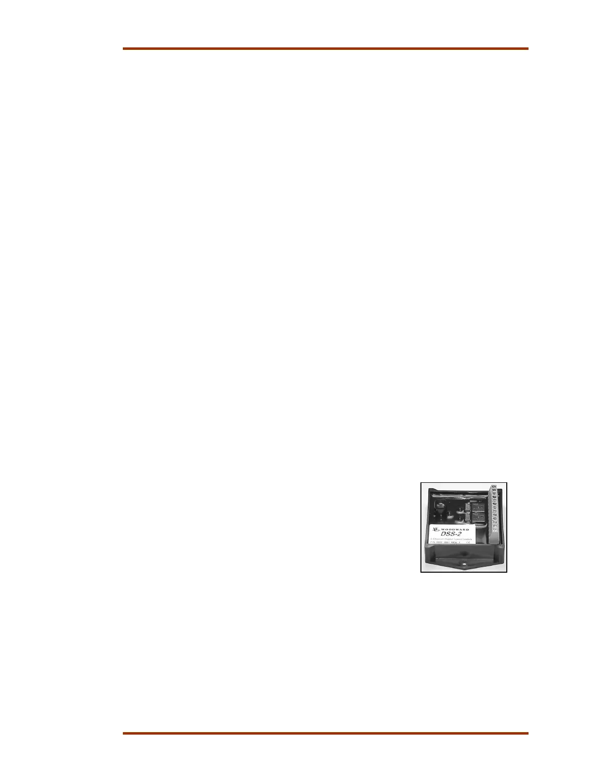
DSS-2 Controller
DSS-2 contains a powerful microcontroller that processes
the signal received from the MPU sensor and compares it
to the speed setpoints. Output control is accomplished by
means of two independently controlled form-C relays with
Common (C), Normally Closed (NC) and Normally Open
(NO) contacts.
The DSS-2 controller has two multi-turn potentiometers
for speed setpoint adjustment. A computer serial
interface is provided for additional adjustments with the ACT.
The controller has thirteen Euro-style screw terminals for:
• Battery Positive and Negative (9-30 Vdc). Reverse voltage protected
• Two form-C relays (10A continuous). Independent Common (C), Normally
Closed (NC) and Normally Open (NO) contacts are provided. DSS-2 is
factory programmed for standard relay logic (relay de-energized below set
speed), but may be modified with the ACT for reverse relay logic (relay
energized below set speed). External diodes should be added for transient
suppression with inductive loads
 Loading...