Do you have a question about the Woodward MFR 13 Series and is the answer not in the manual?
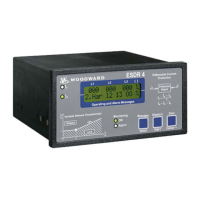
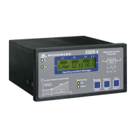
Overview of the MFR 13 Protection Relay and its capabilities.
Details on how voltage, current, frequency, power, and energy are measured and logged.
Overview of functions included in different MFR 13 package options.
Essential safety guidelines to prevent damage to sensitive electronic components.
Schematic illustrating the electrical connections for the MFR 13 unit.
Details on connecting the standard and wide-range power supplies.
Information on connecting voltage measuring inputs.
Guide for connecting current transformer inputs.
Guide for connecting discrete input signals for control and blocking functions.
Description of connections for relay outputs.
Details on connecting the pulse output for kWh measurement.
Information on connecting and configuring analog outputs.
Details on Modbus interface and DPC direct configuration port connections.
Procedure for configuring the unit using a PC and the DPC cable.
Explanation of how discrete inputs control protective functions and acknowledgments.
Description of how relay outputs are assigned to protective functions.
How the unit indicates active power flow direction from the generator.
Explanation of power factor calculation and its display.
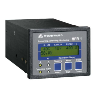
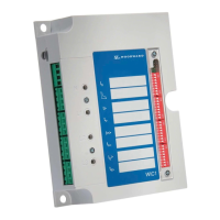
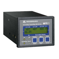
Description of LEDs, push buttons, and the LC display on the unit's front panel.
Explanation of the meaning and behavior of the unit's status LEDs.
Details on how to use the push buttons for navigation and parameter adjustment.
How measured values and alarm indications are shown on the LC display.
Setting software version, language, and access codes.
Configuring user access levels and passwords for system security.
Procedures for configuring the unit using a PC and the DPC cable.
Setting parameters for voltage, current, and power measurements.
Configuration of control functions like synchronization.
Setting parameters for synchronization of power systems.
Selecting voltage monitoring methods (phase-neutral or phase-to-phase).
Setting thresholds, delays, and hysteresis for overvoltage detection.
Setting thresholds, delays, and hysteresis for undervoltage detection.
Configuring parameters for zero voltage detection.
Setting parameters for voltage asymmetry detection.
Setting thresholds, delays, and hysteresis for overfrequency detection.
Setting thresholds, delays, and hysteresis for underfrequency detection.
Configuring step-definite time overcurrent protection parameters.
Setting inverse time overcurrent characteristics and time constants.
Configuring voltage restraint for inverse time overcurrent.
Setting parameters for calculated ground fault current monitoring.
Configuring parameters for positive active load overload detection.
Setting parameters for reverse or reduced power detection.
Configuring parameters for unbalanced load detection.
Setting parameters for capacitive and inductive reactive power monitoring.
Managing relay assignments and auto-acknowledgement settings.
Configuring automatic clearing of alarms and messages.
Defining functionality and assignments for individual relay outputs.
Setting up the pulse output for active energy measurement.
Configuring linear measuring ranges for analog outputs.
Setting up Modbus RTU Slave protocol and general interface parameters.
Step-by-step guide for wiring, configuring, and testing the unit.
Physical dimensions and mounting details of the MFR 13 unit.
Details from the unit's nameplate and general technical specifications.
Electrical ratings and accuracy for voltage and current measurements.
Operating conditions, temperature, and humidity specifications.
Table of measured quantities, their display ranges, and accuracy.
Mapping of Modbus/CAN bus/Profibus addresses to measured values.
Description of data formats for voltage, current, power, and other values.
Details on Modbus RTU Slave connection and framework data.
Comprehensive list of configurable parameters for protection functions.
Parameters for configuring relay outputs and function assignments.
Configuration options for the pulse output.
Configuration options for analog outputs.
Configuration options for communication interfaces.
Overview of available factory options for servicing Woodward equipment.
Instructions for returning units for repair, including packing and authorization.
Details on how to contact Woodward for technical assistance and engineering services.