Do you have a question about the Woodward MRG3 and is the answer not in the manual?
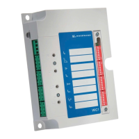
Details the wiring and connection diagrams for the MRG3.
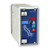
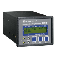
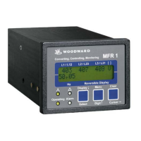
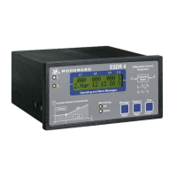
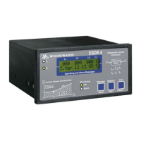
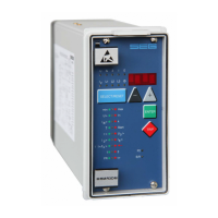
Illustrates the layout and components of the MRG3 front panel.
Explains the function and indication of the device's LEDs.
Describes the analog input signal processing within the MRG3.
Explains the role of the microcontroller and digital processing.
Details the over/under voltage protection functions of the MRG3.
Explains how the MRG3 monitors and protects against frequency deviations.
Covers methods for generator separation from the mains based on frequency or vector surge.
Describes the MRG3's protection against overcurrent and short circuits.
Details the MRG3's earth fault detection and directional features.
Explains the MRG3's capability to record fault data and events.
Shows how measured values and settings are displayed on the MRG3.
Guides the user through the process of configuring MRG3 parameters.
Covers essential system settings like voltage transformer connections and nominal values.
Details the settings for mains decoupling functions like voltage and frequency supervision.
Explains how to configure overcurrent protection settings.
Details the configuration of earth fault supervision parameters.
Covers additional settings such as CB failure protection and communication parameters.
Explains how to adjust and manage the fault recorder settings.
Describes functions like blocking and output relay assignment.
Details how to display various measured values on the MRG3.
Instructions for connecting the auxiliary power supply to the MRG3.
Procedures for testing the MRG3's output relays and status LEDs.
How to verify the configured settings of the MRG3.
Testing procedures using secondary injection for voltage-related functions.
Testing procedures using secondary injection for current-related functions.
A specific test circuit example for earth current directional feature testing.
How to test the external blocking and reset input functions.
Explains the procedure and considerations for primary injection testing.
General guidelines for performing maintenance on MRG3 relays.
Specifies the voltage measurement input parameters and ranges.
Details the parameters and accuracy of frequency measurement.
Specifies the input parameters for phase current measurement.
Details the input parameters for residual voltage measurement.
Specifies the input parameters for earth current measurement.
Lists the configurable parameters with their setting ranges and steps.
Details protection parameter settings for voltage, frequency, and gradient.
Specifies setting ranges for time overcurrent protection characteristics.
Details setting ranges for earth fault supervision parameters.
Specifies setting ranges for directional earth fault supervision.
Details setting ranges for residual voltage protection.
Provides formulas for inverse time overcurrent protection characteristics.
Displays graphical curves for inverse time overcurrent protection.