Do you have a question about the Woodward MFR 15 and is the answer not in the manual?
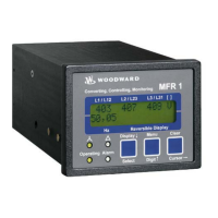
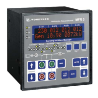
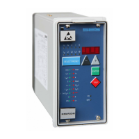
Provides a general overview of the MFR 15 model and its integrated functionalities.
Explains how voltage, current, active power, reactive power, and energy are measured and logged.
Lists the general, protective, and control/synchronization functions offered by the unit.
Outlines essential precautions to prevent damage from electrostatic discharge to electronic components.
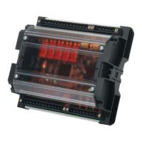
Illustrates the electrical connections for different MFR 15 software versions.
Details the connections for standard and wide-range power supply units.
Describes connections for voltage and current measuring inputs.
Explains the function and connection of discrete and analog control inputs.
Details the connection and function of relay, pulse, and analog outputs.
Explains the configuration and functionality of three-position and analog controller outputs.
Covers settings for serial, CAN, and Profibus DP communication interfaces.
Information on using the DPC cable and software for unit configuration.
Details the functions of various discrete control inputs and relay/analog outputs.
Defines different operational modes like no-load, synchronization, and power control.
Explains power control, power factor control, and direction of power monitoring.
Illustrates the direction of active and reactive power flow from the generator.
Defines power factor, its calculation, and interpretation (inductive vs. capacitive).
Lists alarm messages, their types, and how to acknowledge them.
Describes the physical layout of the unit's front panel, including LEDs and buttons.
Explains how measured values and alarms are displayed on the LC display.
Covers software version, language selection, and initial configuration access.
Details setting up password levels and sealing for secure parameter access.
Instructions for performing unit configuration using PC software via DPC.
Configuration of voltage, current, and power measurement parameters and transformer ratios.
Settings for synchronization, frequency, voltage, active power, and reactive power controllers.
Configuration of various protection functions like over/undervoltage, frequency, and current monitoring.
Step-by-step guide for safely installing and verifying the unit's operation.
Provides physical dimensions, front cutout, and mounting details.
Lists electrical specifications, input/output ranges, and ambient operating conditions.
Details the accuracy and display ranges for measured quantities like frequency, voltage, and current.
Maps telegram addresses for Modbus, CAN bus, and Profibus communication.
Explains data formats, scaling, and provides examples for interface communication.
Provides technical details and procedures for TTY, RS232, RS485, Modbus, CAN, and Profibus interfaces.
A comprehensive table listing all available parameters, their settings, and default values.
Information on factory service options, returning equipment, and contacting support.
Details on available engineering services and technical assistance.