EasyManua.ls Logo

Woodward ProTech-GII 8237-1594 User Manual

Woodward ProTech-GII 8237-1594
207 pages
To Next Page IconTo Next Page
Page #1 background imageLoading...
Page #1 background image
®
Product Manual 26709
(Revision F, 10/2016)
Original Instructions
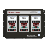
ProTech-GII Overspeed Protection Device
with Voted Inputs
8237-1594, -1595, -1596, -1597, -1598, -1599,
-1600, -1601, -1656, -1660
Installation and Operation Manual

Table of Contents

Questions and Answers:

Woodward ProTech-GII 8237-1594 Specifications

General IconGeneral
BrandWoodward
ModelProTech-GII 8237-1594
CategorySecurity Sensors
LanguageEnglish

Summary

Warnings and Notices

General Safety Precautions

Covers overspeed, PPE, start-up, and battery safety guidelines.

Important Definitions

Describes safety alert symbols and their meanings.

Electrostatic Discharge Awareness

Electrostatic Precautions

Steps to prevent damage to electronic components from static electricity.

Regulatory Compliance

European Compliance

CE, EMC, Low Voltage, and ATEX directives and standards.

North American Compliance

CSA certification details for North American use.

International Compliance

C-Tick, TÜV, Gas Corrosion, and Machinery Protection standards.

Special Conditions for Safe Use

Safe Use Environment and Wiring

Specifies location, wiring, and grounding requirements for safe operation.

Safety Symbols

Common Safety Symbols

Explains electrical symbols for current, shock risk, and documentation.

Acronyms and Definitions

Glossary of Terms

Lists abbreviations and their meanings used in the manual.

Chapter 1. General Information

Description

Overview of the ProTech-GII device, its function, and architecture.

Applications

Details the typical applications and industries where the ProTech-GII is used.

Chapter 2. Installation

Hardware Installation Procedure

Steps for mechanical and electrical installation of the device.

Enclosures

Describes bulkhead and panel mount enclosure types and features.

Module Removal and Installation—Bulkhead Mount Package

Bulkhead Mount Module Handling

Procedures for safely removing and installing bulkhead mount modules.

Module Removal and Installation—Panel Mount Package

Panel Mount Module Handling

Procedures for safely removing and installing panel mount modules.

Mounting Location Considerations

Environmental and Mounting Factors

Guidelines for selecting a suitable installation location for optimal performance.

Environmental Specifications

Operating and Storage Conditions

Details temperature, humidity, vibration, and other environmental limits.

Power Supply Requirements

Input Power Specifications

Details voltage, current, protection, and interrupt time for power inputs.

Input/Output Specifications

Speed Input Specifications

Details for passive MPU and active speed probes.

Relay Specifications

Details for trip and alarm relay outputs.

Shielded Wiring

Wiring Practices for EMI

Guidelines for using shielded cables to prevent electromagnetic interference.

Control Wiring Guidelines

Electrical Connections and Wire Gauge

Wire size, stripping, torque, and terminal block usage for connections.

Field Wiring Access and Separation

Wiring Practices for Bulkhead and Panel Mounts

How to route wires for different enclosure types, considering EMI.

Speed Sensor Inputs

MPU, Proximity, and Eddy Current Probes

How different speed sensors work and are wired to the module.

Dedicated Discrete Inputs

Start, Reset, and Speed-Fail-Override Inputs

Functionality and wiring of the three dedicated discrete inputs.

Relay Outputs

Independent Trip Relay Outputs

Wiring details for models with independent trip relay outputs.

Voted Trip Relay Outputs

Wiring details for models with voted trip relay outputs.

Alarm Relay Output

Alarm Relay Wiring

Wiring details for the module's alarm relay output.

Serial Modbus Communications

Modbus Port Functionality

Using the serial port for Modbus communication with external systems.

Service Port Communications

PCT Connection

Connecting a computer using the PCT for configuration and data retrieval.

Chapter 3. Functionality

Introduction

Overview of the ProTech-GII's primary functions and capabilities.

Features

Key features including fault tolerance and triple modular redundancy.

Configuration Overview

Module-to-Module Sharing Logic

How modules share data, inputs, and configurations via the CAN network.

Security

Password Levels and Defaults

Explanation of Test and Config level passwords and their default values.

Product Models

Independent vs. Voted Trip Relay Models

Differences between Independent and Voted Trip Relay models.

Inputs and Outputs

Input Redundancy

How speed input signals can be configured for redundancy.

Speed Sensor Inputs

Speed Probe Configuration and Voting

Configuring speed probes and using them with redundancy managers.

Dedicated Discrete Inputs

Input Sharing Configuration

Configuring sharing for Start, Reset, and Speed Fail Override inputs.

Overspeed and Over-Acceleration Detection Logic

Trip Logic and Setpoints

How overspeed and over-acceleration events are detected and trigger trips.

Speed Redundancy Manager

Speed Signal Selection and Voting

Configuring how speed signals are selected and voted for redundancy.

Acceleration Redundancy Manager

Acceleration Signal Selection and Voting

Configuring how acceleration signals are selected and voted for redundancy.

Start Logic

Speed Fail Detection and Override Logic

Logic for detecting speed failures during start-up and override functions.

Speed Fail Trip

Speed Fail Trip Diagram and Logic

How the speed fail trip function is implemented and its logic.

Speed Fail Timeout Trip

Speed Fail Timeout Logic

Logic for timing out during start-up if speed is not detected.

Test Routines

Temporary Overspeed Setpoint Test

How to test overspeed with a temporary setpoint adjustment.

Simulated Speed Tests

Manual Simulated Speed Test

Procedure for manually simulating speed for testing purposes.

Auto Simulated Speed Test

Procedure for automated speed simulations for testing purposes.

Auto Sequence Test

Automating tests across modules sequentially.

Alarm and Trip Latches

Reset Function

How to reset latched alarms and trip conditions.

Alarm Latch Logic

How alarm conditions are latched and indicated.

Trip Latch

Trip Latch Logic and States

How trip conditions are latched and indicated.

System Logs

Log Management and Clearing

How logs are stored, viewed, and cleared.

ProTech-GII Response Time Performance

Response Time Graphs and Definitions

Performance data and definitions for various configurations.

Chapter 4. Front Panel Interface

Introduction

Overview of the front panel's capabilities for monitoring and control.

Screen Layout

ProTech-GII Screen Structure

Explanation of screen elements like name, data, annunciation, and soft keys.

Keypad Functions

Front Panel Key Operations

How each key and indicator on the front panel functions.

Navigation

Menu Navigation and Home Screen

How to move through menus and the function of the Home screen.

Passwords

Test and Config Level Passwords

Explanation of password protection levels and default passwords.

Monitor Menu

Available Monitor Screens

List of data views accessible from the Monitor Menu.

Monitor Summary Page

Displayed Summary Data

Overview of sensed speed, acceleration, and status information.

Monitor Trip Latch Page

Trip Latch Status

Shows the status of each trip latch input.

Monitor Alarm Latch Page

Alarm Latch Status

Shows the status of each alarm latch input.

Monitor Dedicated Discrete Inputs Page

Discrete Input Status

Shows the status of Start, Reset, and Speed Fail Override inputs.

Monitor Speed Redundancy Manager Page

Speed Redundancy Manager Status

Monitoring speed signal inputs and redundancy logic.

Monitor Acceleration Redundancy Manager Page

Acceleration Redundancy Manager Status

Monitoring acceleration signal inputs and redundancy logic.

Monitor Speed Fail Timer Page

Speed Fail Timer Status

Monitoring the speed fail timer function.

Monitor Analog Output Page

Analog Output Monitoring

Viewing the analog output signal and its scaling.

Monitor Modbus Page

Modbus Link Status

Checking the status of the Modbus communication port.

Monitor/Set Date & Time Page

Date and Time Settings

Viewing and setting the device's current date and time.

Time & Date Change Procedure

Setting the Device Time and Date

Step-by-step guide to changing the device's date and time.

Monitor System Status Page

Module Health Status

Checking the operational health status of each module.

Module Information Page

Product Identification

Viewing product ID, serial number, and software version.

View Logs

Logs Menu

Accessing different types of event logs like Trip, Alarm, and Overspeed.

Overspeed/Acceleration Log Page

Overspeed/Acceleration Event Logging

Details of logged overspeed and over-acceleration events.

Trip Log Page

Trip Event Logging

Details of logged trip events, including first-out indications.

Alarm Log Page

Alarm Event Logging

Details of logged alarm events.

Peak Speed/Acceleration Log Page

Peak Speed/Acceleration Logging

Logging of maximum speed and acceleration values since last reset.

Reset Logs Page

Log Reset Procedure

How to clear logged data from the device.

Chapter 5. Configuration of the ProTech-GII via Front Panel

Introduction

Overview of front panel configuration methods.

Editing Configuration Settings from the Front Panel

Process for changing settings via the keypad interface.

Configure Menu Page

Configure Menu Descriptions

Explains each option within the Configure Menu.

Configuration Procedure

Step-by-Step Configuration Process

Detailed steps to perform configuration via the front panel.

Configure Language Page

Language Selection

How to set the display language for the ProTech-GII.

Configure Speed Submenu Page

Speed Configuration Options

Accessing speed, acceleration, and redundancy settings.

Configure Speed Input Page

Speed Input and Trip Settings

Configuring probe type, gear teeth, ratio, and overspeed trip.

Configure Acceleration Page

Acceleration Trip Configuration

Enabling and setting over-acceleration trip parameters.

Configure Start Logic Page

Start Logic and Speed Fail Settings

Configuring speed fail detection and timeout logic.

Configure Speed Redundancy Manager Page

Speed Redundancy Configuration

Setting up speed signal selection and voting for redundancy.

Configure Acceleration Redundancy Manager Page

Acceleration Redundancy Configuration

Setting up acceleration signal selection and voting for redundancy.

Configure Trip Latch Page

Trip Latch Configuration

Setting trip actions (energize/de-energize) and latch output behavior.

Configure Alarm Latch Page

Alarm Latch Configuration

Configuring how trip states affect the alarm latch logic.

Configure Dedicated Discrete Submenu Page

Discrete Input Sharing Configuration

Configuring sharing for Start, Reset, and Speed Fail Override inputs.

Configure Start Input Sharing Page

Start Input Sharing Settings

Configuring which modules can provide the Start signal.

Configure Reset Input Sharing Page

Reset Input Sharing Settings

Configuring which modules can provide the Reset signal.

Configure Speed Fail Override Input Sharing Page

Speed Fail Override Input Sharing Settings

Configuring which modules can provide the Speed Fail Override signal.

Configure Analog Output Page

Analog Output Scaling

Setting the speed values for 4mA and 20mA analog output scaling.

Configure Test Modes Page

Test Mode Settings

Configuring temporary overspeed tests, timeouts, and permissives.

Configure Auto-Sequence Test Page

Auto-Sequence Test Configuration

Setting up periodic automated testing of modules.

Configure Modbus Page

Modbus Communication Settings

Configuring Modbus mode, baud rate, parity, and slave address.

Configure Power Supply Alarms Page

Power Supply Fault Alarm Configuration

Enabling or disabling alarms for power supply faults.

Configure Display Page

Display Behavior Settings

Configuring screen action on trip and the home screen.

Configuration Management Menu Page

Configuration Management Options

Overview, compare, and copy functions for configuration.

Configuration Overview Page

CRC Code Display

Showing CRC codes for configuration integrity checks.

Configure Configuration Compare Page

Module Configuration Comparison

Enabling/disabling comparison alarms and viewing differences.

Configuration Copy Page

Copying Configuration Between Modules

Verifying and copying settings to other modules.

Password Change Menu Page

Password Management

Changing Test and Config level passwords.

Chapter 6. Test Routines

Test Modes Menu

Accessing all available test routines from the front panel.

Temporary Overspeed Setpoint Test

Temporary Overspeed Test Procedure

Steps for performing the temporary overspeed test.

Manual Simulated Speed Test

Manual Speed Simulation Testing

Procedure for manually simulating speed for testing purposes.

Auto Simulated Speed Test

Auto Simulated Speed Test Procedure

Procedure for automated speed simulation testing.

Auto-Sequence Test

Auto-Sequence Test Procedure

Procedure for sequential automated testing of modules.

Lamp Test

Front Panel LED Test

Testing the functionality of front panel LEDs.

General Testing Notes

Test Mode Permissive Settings

Restrictions on running tests based on module states.

Chapter 7. Programming and Configuration Tool

General PCT Usage

Overview of configuring the ProTech-GII using the PCT software.

Installation of the PCT

PCT Software Installation

Steps to install the Programming and Configuration Tool software.

Levels of Operation of the Programming and Configuration Tool (PCT)

PCT Operating Modes

Isolated, Test, and Config levels of PCT operation.

Using the Programming and Configuration Tool (PCT)

PCT Connection and Login

Establishing communication and logging into the PCT software.

On-Line Menu

On-Line Menu Options

Functions available when connected online via PCT.

View Configuration Error Log

Configuration Error Log Details

Viewing detected configuration faults and errors.

Data Entry Errors

Handling Invalid Data Entries

How errors are displayed when editing settings.

View Trip and Alarm Log

Trip and Alarm Log Review

Viewing logged trip and alarm events via PCT.

View Overspeed/Acceleration Log

Overspeed/Acceleration Log Review

Viewing logged overspeed and acceleration events via PCT.

View Module Faults Log

Module Faults Log Details

Viewing detailed internal fault information via PCT.

Configuration Overview

CRC Code Display

Showing CRC codes for configuration integrity checks.

Parameter Block Definitions

Parameter Block CRC Descriptions

Definitions of CRC codes for various configuration parameters.

Off-Line Menu

Edit/View Configuration

Modifying configuration files offline using the PCT.

On-Line Configuration

On-Line Parameter Configuration

Changing parameters while the ProTech-GII is operational.

Configuration Settings – PCT

PCT Configuration Parameter Settings

Details of parameters configurable via PCT.

Creating and Modifying Configuration Files

PCT Configuration File Management

Using PCT to create, save, and modify settings files.

Edit Settings File

Modifying Existing Configuration Files

Process for editing saved configuration files.

Load Settings File to Device

Uploading Configuration to ProTech-GII

Steps to load configuration files into the device.

Compare Settings File Differences

Comparing Configuration Files

Comparing configuration files for differences.

Speed and Redundancy Management

Speed Input and Redundancy Settings

Configuring speed input type and redundancy manager settings.

Start Logic & Power Supply Alarms

Start Logic and Power Supply Alarm Configuration

Setting start logic parameters and power supply fault alarms.

Discrete Inputs

Discrete Input Sharing Configuration

Configuring sharing for discrete inputs.

Modbus

Modbus Communication Configuration

Configuring Modbus parameters like mode and baud rate.

Test Modes

Configuring Test Mode Parameters

Setting up temporary overspeed, simulated speed, and sequence tests.

ProTech-GII Configuration Checks

Configuration Error Handling

How configuration issues are detected and reported.

Chapter 8. Modbus Communications

Introduction to Modbus

Overview of Modbus protocol and ProTech-GII communication.

Port Adjustments

Modbus Communication Port Settings

Configuring Modbus port parameters like mode and baud rate.

ProTech-GII Parameter Addresses

Modbus Parameter Address List

List of Modbus addresses for parameters.

Chapter 9. Safety Management

Product Variations Certified

Safety certifications for ProTech-GII models.

Safe State Configuration

How the device behaves in safe and unsafe states.

SIL Specifications

Safety Integrity Level (SIL) Values

SIL ratings and related failure data.

Management of Functional Safety

Safety Lifecycle Requirements

How the ProTech-GII fits into safety lifecycle management.

Restrictions

Usage and Configuration Restrictions

Limitations and requirements for proper device use and configuration.

Operation and Maintenance Practice

Periodic Proof Testing Requirements

Guidelines for performing periodic functional testing.

Functional Testing after Initial Installation

Initial Safety System Functional Test

Required functional testing after initial installation.

Functional Testing after Changes

Testing After Configuration Changes

Importance of re-testing after making configuration changes.

Proof Testing (Functional Test)

ProTech-GII Proof Test Procedure

Detailed steps for periodic proof testing of the device.

Chapter 10. Troubleshooting

Introduction to Troubleshooting

General approach to troubleshooting the ProTech-GII.

I/O Troubleshooting

Troubleshooting Input/Output Issues

Common I/O problems and suggested actions.

Trip Indications

Diagnosing Trip Events

Interpreting trip indications and their possible causes.

Alarm Indications

Diagnosing Alarm Events

Interpreting alarm indications and their possible causes.

Chapter 11. ProTech-GII Configuration Worksheet

Speed Input Configuration Parameters

Worksheet section for configuring speed input settings.

ACCELERATION REDUNDANCY MANAGER

Acceleration Redundancy Parameters

Worksheet section for configuring acceleration redundancy.

DISCRETE INPUTS

Discrete Input Sharing Parameters

Worksheet section for configuring discrete input sharing.

START LOGIC

Start Logic Parameters

Worksheet section for configuring start logic settings.

TRIP LATCH

Trip Latch Parameters

Worksheet section for configuring trip latch settings.

Chapter 12. Product Support and Service Options

Product Support Options

Ways to get help with Woodward products.

Product Service Options

Available factory service options like replacement and repair.

Returning Equipment for Repair

Procedures for Returning Equipment

Instructions for returning units for service, including packing.

Replacement Parts

Ordering Replacement Parts

Information needed when ordering replacement parts.

Engineering Services

Available Engineering Services

Technical support, product training, and field service options.

Chapter 13. Asset Management

Product Storage Recommendations

Guidelines for storing the unit in its original container.

Refurbishment Period Recommendation

Recommendations for periodic inspection and component upgrades.

Appendix. Modbus Ethernet Gateway Information

Introduction to Gateways

Recommended Ethernet-to-Serial gateways for Modbus communication.

Wiring

RS-232 and RS-485 Wiring Diagrams

Visual guides for connecting gateways via RS-232 and RS-485.

Configuration

MESR901 Gateway Configuration

Steps to configure the B&B Electronics MESR901 gateway.

Serial Communication Settings

Lantronix Gateway Setup

Steps to configure the Lantronix UDS100 gateway.

Configuration

UDS100-Xpress DR IAP Configuration

Software steps for configuring the Lantronix gateway.

Serial Settings Menu

Serial Communication Configuration Options

Settings for RS-485 and RS-232 communication.

Advanced Menu

Advanced Gateway Configuration Options

Accessing advanced settings for the gateway.

Revision History

Document Revision Changes

Summary of changes made across different revisions of the manual.

Declarations

EU Declaration of Conformity

Regulatory compliance statement for the European Union.

Related product manuals