1
0.5.
FINAL
INSTALLATION
Remove
the automatic
air
vent cap.
See
Fig.
1
9.
Replace
the inner
casing
coVEr.
See
Fig.
22.
Check
that
all
the gas and water connections
on
the
manifold
have
been
ti
ghtened.
Remove
the
fa
cia
panel as described
in
Section
14.2
(a).
Facia Mounted Programmer
Unplug the Operating Switch connection at the control board.
Unscrew
and retain the
four
nuts and washers securing the switch
mounting plate to the
facia
.
See
Fig.
40
.
Remove
the plate.
Fit
the
programmer to the
facia
and
fix
using the
four
nuts and washers.
Plug
the lead into the connection
X14
on
the main driver board.
See
Fig.
9b
.
The
programmer can be set when the electricity sup·
ply has been turned on at the commissioning stage.
Connect
the mains electricity supply to the appliance and connect
any room and/ or
frost
thermostats.
Refer
to
Section
9,
Figs.
7 and
8.
The
leads
from
the thermostats must pass through the holes
provided
in
the control box at the right hand side and be clamped
using the strain
relief
bushes provided
in
the pack.
Check
that the
control box can be withdrawn and
lowered
before
fixing
any
leads
outs
ide
the appliance.
To
remove
t
he
control box
refer
to
Section
14.2
(b).
Refit
the control
box
and
facia.
Test
the gas supply
for
soundness as indicated
in
BS
6891
.
If the appliance
is
not to be commissioned immediately, replace
the inner cover panel and the cabinet front pan
el.
See
Fig
.
22
.
Check
that the gas supply, the
electrical
supply and the water
con
-
nections are a
ll
turned
off
.
11
. Commissioning
11
. 1
The
appliance
is
despatched
with
the controls set to
provide
a maximum output
for
domestic hot water
of
35.
2kW
(120,000
Btu
/
h)
and satisfy a central heating load up to 15kW
(51
,200
Btu
/
h)
.
The
controls can be reset to increase the central heating
load capability up
to
25kW
(85
,300
Btu
/
h)
.
It
is
no
t necessary to
set an output betw
ee
n these
figures.
Domestic Hot Water System
Confirm
that the mains water supply has been
fully
flushed
out at
installation.
If
not,
it
will
be necessary
to
disconnect the
cold
water
inlet
pipe
from
the appliance and thoroughly
flush
.
Central Heating System
Confirm
that t
he
central
he
ating system has been
fully
flushed
out
at
in
stallation
usin
g a flushing agent.
If
not, after the addition
of
a
su
it
able
flushing
agent, drain whilst hot and immediately
refill
and
re-pressurise. A suitable proprietary inhibitor should be added
when
refilling.
Further
information
can be obtained
from
Worcester
Heat
Systems.
11.2
APPLIANCE AND SYSTEM PREPARATION.
Check
that the gas service and the electrical supply to the appli-
ance are o
ff
.
Check
that the
Operating
Sw
itch
(or
progr
ammer)
is
set
to
OFF
.
Se
e
Fig
.
20.
Check
that
all
the water connections throughout the system are
tight.
Remove
the cabinet
fr
ont panel
by
pu;lling forward at the
bottom and
lifting
it
off
the top supports.
Remove
the inner
cover
panel
by
uns
crewin
g the
four
screws.
See
Fig.
22.
Unscrew
the two screws at each
en
d
of
the control box.
Pu
ll
for
-
ward and
low
er the control box assemb
ly
. S
ee
Fig.
22.
Open
the central heating system
valves
on the
manifold.
See
Fig
.
21.
Open
all
the radiator valves and
fill
the system.
The
automatic
air vent
(fixed
to the
flow
manifold)
will
vent the appliance.
See
Fig.
1
9.
Remove
the
boiler
inner casing
co
ve
r
to
check that the
air
vent
16
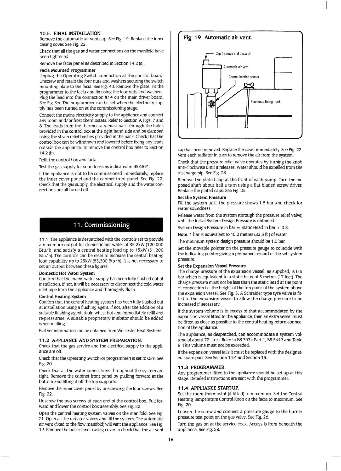
Fig. 1
9.
Automatic air vent.
Flue
hood
fixing
hook
cap has been
removed.
Replace
the
cover
immediately.
See
Fig
.
22
.
Vent
each radiator
in
tum to remove the air
from
the system.
Check
that the pressure
relie
f
valve
operates
by
turning the knob
anti
-clockwise
until
it
releases.
Water
should be expelled
from
the
discharge
pip.
See
Fig.
28.
Remove
the plated cap at the front of each pump.
1\Jrn
the
ex-
posed shaft about half a
tum
using a flat bladed screw driver.
Replace
the plated caps.
See
Fig.
25.
Set the System Pressure
Fill
the system until the pressure shows 1 .5 bar and check
for
water soundness.
Release
water
from
the system (through the pressure
relief
valve
)
until the
Initial
System
Design
Pressure
is
obtained.
Syst
em
Design
Pressure
in
bar = Static
Head
in
bar + 0.3.
Note. 1 bar
is
equivalent
to
10.2
metres
(33
.5
ft
.)
of
water.
The
minimum system design pressure should be 1
.0
bar.
Set
the movable pointer
on
the pressure gauge to coincide with
the indicating pointer
giving
a permanent
record
of the set system
pressure.
Set the Expansion Vessel Pressure
The
charge pressure
of
the expansion vesse
l,
as supplied,
is
0.5
bar
wh
ich
is
equivalent
to
a static head
of
5 metres (17
feet)
.
The
charge pressure must not be less than the static head at the point
of connection
i.e.
the height
of
the top point of the system above
the expansion vessel.
See
Fig
. 5. A Schraider type tyre
valve
is
fit-
ted
to
the expansion vessel to allow the charge pressure to
be
increased
if
necessary.
If
the system volume
is
in
excess
of
that accommodated by the
expansion vessel fitted to the appliance, then
an
ex
tra vessel must
be fitted as close as possible
to
the central heating return connec-
tion of the appliance.
The
appliance, as despatched, can accommodate a system val·
ume of about
72
litres.
Refer
to
BS
707 4 Part
1,
BS
5449 and
Table
8.
This
volume must not
be
exceeded.
If
the expansion vessel
fails
it
must be replaced with the designa
t-
ed spare part.
See
Section
14.4 and Section
15.
11.3
PROGRAMMER.
Any
programmer fitted
to
the appliance should be set up at this
stage.
Detailed
instructions are sent with the programmer.
11
.4
APPLIANCE
START·UP.
Set the room thermostat
(if
fitted) to maximum. Set the Central
Heating
Temp
erature
Control
Knob
on
the
facia
to maximum.
See
Fig
. 20.
Loosen the screw and connect a pressure gauge to the burner
pressure test point on the gas
valve
.
See
Fig
.
26
.
1\Jm
the gas on at the service cock.
Access
is
from
beneath the
appliance.
See
Fig.
28.
 Loading...


