Use new seals and gaskets where necessary. Refill and pressurise
as described in Section 12.4-8 - Commissioning. Refer to Fig 59.
15.4.23. Auto Air Vent
Remove the inner casing cover.
Drain the primary system. Refer to 15.3.1. Unscrew and remove
the auto air vent. Remove the cap from the newly fitted vent.
Refill and pressurise as described in Section 12.4-8 -
Commissioning. Refer to Fig 35.
15.4.24. Primary Gas to Water Heat Exchanger
Remove the inner casing cover.
Drain the primary system. Refer to 15.3.1. Remove the fan
assembly, flue hood, CH sensor (at the left hand side) and
overheat thermostat from the heat exchanger. Disconnect the
heat exchanger at the back panel by releasing clips at the right
and left hand sides. Refer to Fig 60.
Withdraw the heat exchanger from the appliance. Note: There
will be a small amount of water still in the heat exchanger. Use
new seals and gaskets where necessary. Refill and pressurise as
described in Section 12.4-8 - Commissioning.
15.4.25. Air Pressure Switch
Remove the inner casing cover.
Remove the switch by carefully prising away from the mounting
tabs of the 'horseshoe' bracket.
Ensure that the connections are correctly made to the new
switch. Refer to Fig. 61.
24
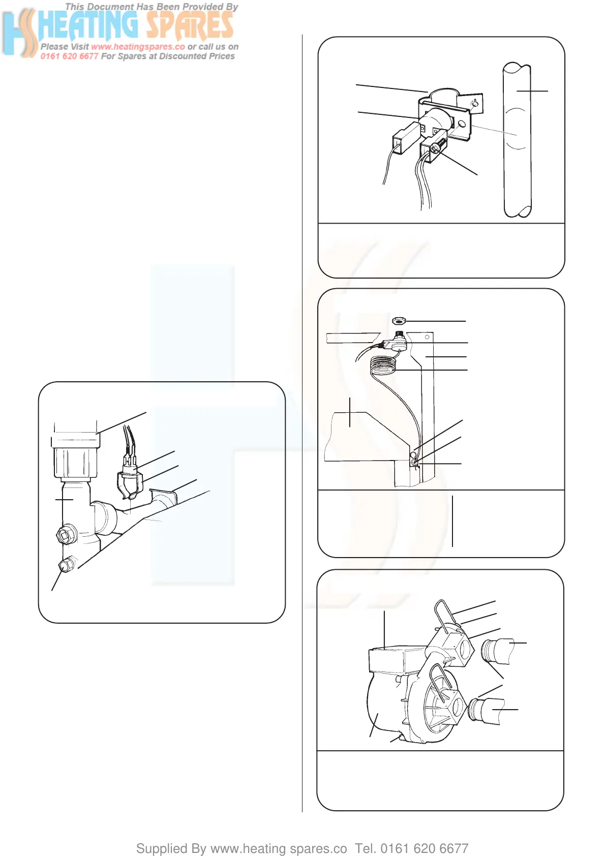
Fig 55-Primary (CH) Sensor
Fig 56-Domestic Hot Water Sensor
Fig 57-Boiler Overheat Thermostat
1
2
3
4
5
6
1. Auto Air Vent
2. Primary (Central Heating)
Sensor
3. Fixing Clamp
4. Primary Heat Exchanger Clip
5. Primary Flow Manifold
6. Primary Flow Manifold Fixing
Screw (1)
1
2
3
4
1. Domestic Hot Water Sensor
2. Fixing Clamp
3. Clamp Fixing Screw
4. Domestic Hot Water Flow Pipe
1
2
3
4
5
6
7
8
1. Lock Nut 6. Thermostat Phial
2. Overheat Thermostat Head 7. Thermostat Pocket
3. Boiler Inner casing 8. Flue Hood
4. Thermostat Capillary
5. Thermostat Capillary Clip
Fig 58-Pump Fixing-Rear View
2
1
4
5
7
7
6
8
3
1. Pump Body 5. Non-Return Valve Test Button
2. Electric Connections 6. O-Ring
Covers 7. Back Panel Connectors
3. Non-Return Valve 8. Pump Body Fixing Screws (3)
4. Fixing Clip (2)