If more than two extension ducts are needed in any section to
achieve the required length then the final section of the
assembly must not be less than 325mm without cutting the
terminal assembly.
NOTE: The flue duct of the final extension must be 30mm longer
than the air duct.
Each section must be connected to the previous section of the
flue bend by fixing the flue ducts together and then similarly
fixing the air ducts which engage the elbows.
Fit the assembly as described in Section 11.9, 11.10 as
appropriate.
Make good the internal and external brickwork or rendering.
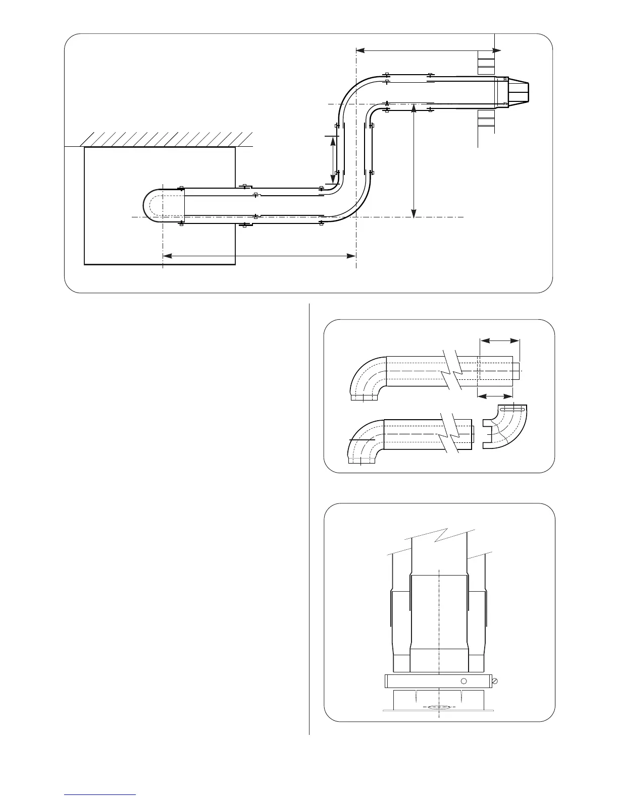
11.13 Vertical Adapter for Horizontal Flues.
An adapter is available for an initial short section of vertical flue.
Refer to Fig. 28.
Measure and cut the flue as described in Section 11.11.
The first, vertical, section (equivalent to dimension X) is
measured from the top of the boiler casing. Cut the vertical
section of the extension duct to 167mm less than the measured
distance. Do not remove the socketed ends.
The minimum measured distance is 167mm.
Seal the air duct to the spigot using silicone sealant.
Fix the adaptor with the clamp and screw provided.
11.14 Completion of the Installation.
Check that all the connections on the manifold have been
tightened. Refer to Fig.6.
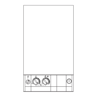
Remove the facia bottom panel. Refer to Fig.29.
Connect the mains electricity supply lead to the appliance and
secure the cable clamp. Refer to Fig.14.
Check there is sufficient loose lead to allow the release of the
facia panel assembly and that the earth lead of the mains supply
cable is longer than the live and neutral leads.
Fit the facia mounted programmer. Refer to Fig.31.
Connect any external controls ensuring that the leads pass
through the appropriate clamps. refer to Fig.32.
Test for gas soundness as described in BS6891.
If the appliance is not commissioned immediately, replace the
cabinet and facia bottom panel. Check that the gas and
electricity services have been turned off.
16
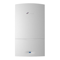
Fig.26. Flue bends
X
Z
Y
Y-162
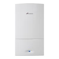
Plain tube
120mm
100mm
Fig.27 - Elbow to Flue Turret
Assembly.
Fig.28 Vertical Adapter.
Flue Duct
Air Duct
Adapter
Clamp
Flue Spigot
Flue Turret
Bend