17
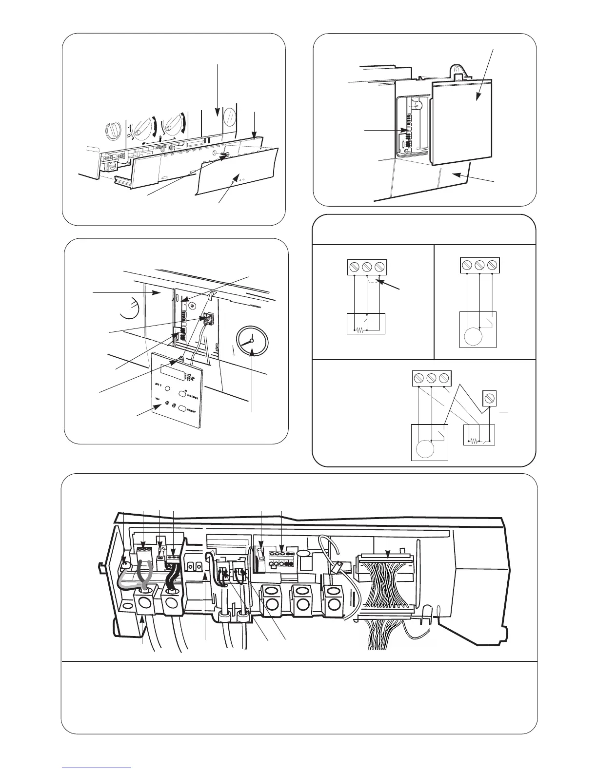
Fig.29. Facia connections cover
Facia
Controls
connections
cover
Fixing screw
Facia bottom panel
(clip-on)
Fig.30. Programmer cover
Cover panel
Facia
Programmer
connections
Fig.31. Programmer connection
Fig.33. Facia connections
Facia
Programmer
connector
Programmer
connections
Clip
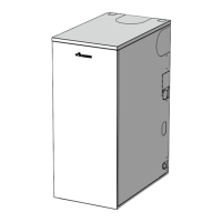
Programmer
Pressure gauge
Control
board
1
2
3
4 5
6
7
8
9
10
1. Earth screw
2. Mains connection (L N)
3. Fuse F1
4. Mains voltage room thermostat/external control-mains
voltage ST8
5. Fuse F2
6. Controls 24V - ST13
7. Mains harness
8. Fan ST1
9. Pump ST5
10. Earth tag
11. Cable clamps (threaded)
11
Fig 32 - Mains Voltage External Controls Connections
230 V Room Thermostat Connections
Ns
Ls
LR
ST8
Ns
Ls
L
R
ST8
Remove Link
Neutral
Live
Switched Live
Neutral
Live
Switched Live
Motor
230 V Programmer Connections
230 V room thermostat and
Programmer Connections
Ns
Ls
L
R
ST8
Neutral
Live
Neutral
Live
Switched Live
Motor
Switched Live
Series
connection
to be made
safe
NOTE: Only double insulated controls not requiring an earth can be used