18
System pressure
Greenstar i System
ErP
– 6 720 806 947 (2015/03)
4System pressure
4.1 External filling link
This appliance is fitted to a sealed heating system which is pressurised. Your installer will advise you of the minimum and maximum
pressure indicated on the pressure gauge.
▶ Check regularly that the pressure is maintained.
▶ If the pressure gauge reads less than 1 bar then the system requires re-charging.
▶ Contact your installer or maintenance engineer if a permanent significant decrease or increase in pressure is indicated on the
pressure gauge.
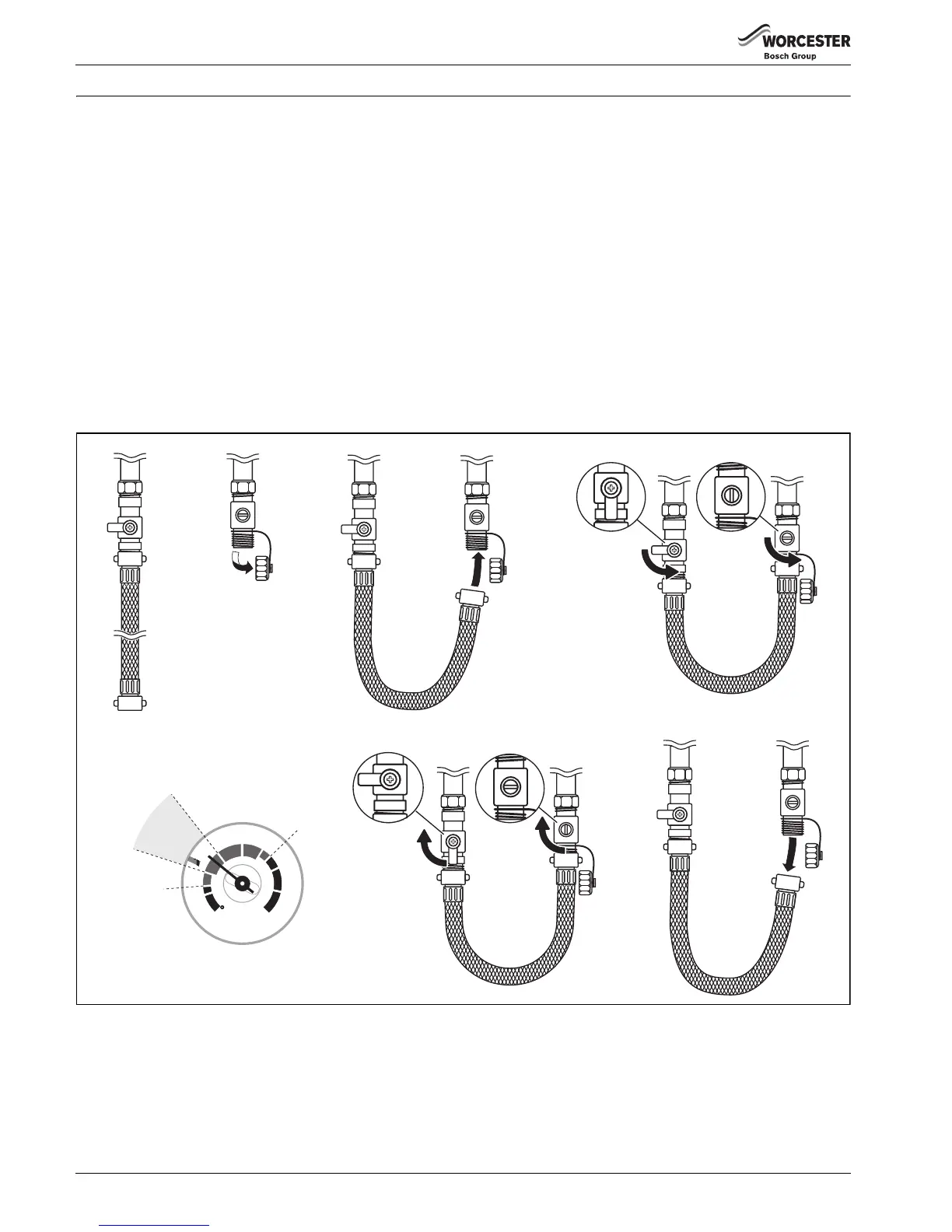
Once the external filling loop has been located, follow the instructions for re-pressurising the system.
1. Unscrew blanking cap.
2. Attach the hose to the valves, screw on hand-tight.
3. Turn the handle/screwdriver slot through 90° to open the valves.
4. The handle/screwdriver slot will be in-line with the valves
Fig. 10 External filling loop
5. When the pressure reaches between the 1 and 1.5 bar marks (zone A), turn the handle/screwdriver slot back, through 90°, to
close the valve.
6. The handle/screwdriver slot will be at 90° to the valves
7. Remove the hose and replace the blanking caps.
 Loading...