INSTALLATION
INSTALLATION & SERVICING INSTRUCTIONS
23
FLUE CONNECTIONS
6-720-611-730b (12.05)
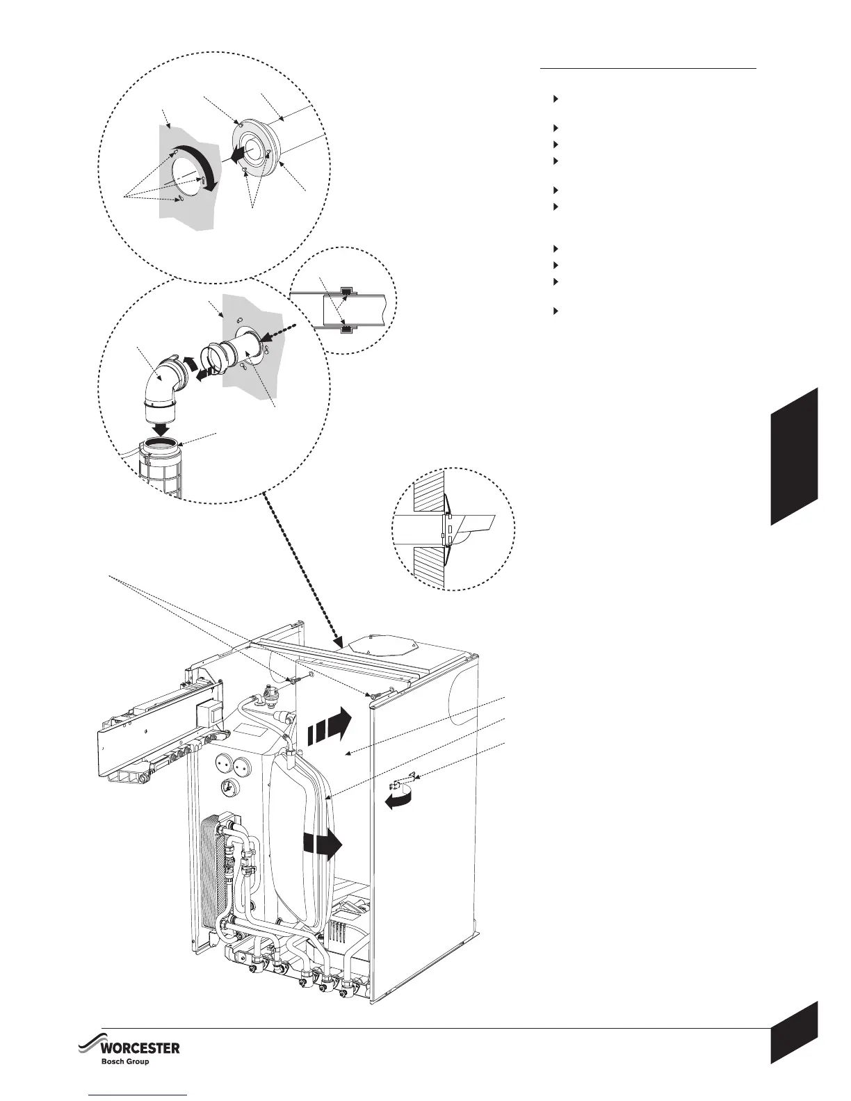
FLUE CONNECTIONS
1 Align the flue retaining ring (D) to the boiler
internal casing (B)
Locate screws (A) into keyhole slots (C)
2
Rotate flue retaining ring (D) to lock into position
Tighten screws (A) to secure flue (H) to boiler
internal casing (B)
3
Insert and push elbow (E) into flue adapter (F)
4
Pull the elbow extension tube (G) and clip to
flue elbow (E) ensuring that the sealing rings (J)
are still in contact with the inner flue tube
5
Refit inner case cover (L)
Secure using 4 screws (K)
6
Swing expansion vessel (M) inwards and
secure with clip (N)
7
Ensure that the slope of the terminal outlet
(outside) faces downwards as shown.
G
B
C
A
A
B
5
1
2
D
H
F
E
J
M
K
6
N
L
3
4
7
D
 Loading...


