SERVICING
& SPARES
INSTALLATION & SERVICING INSTRUCTIONS
38
REPLACEMENT PARTS
6-720-611-730b (12.05)
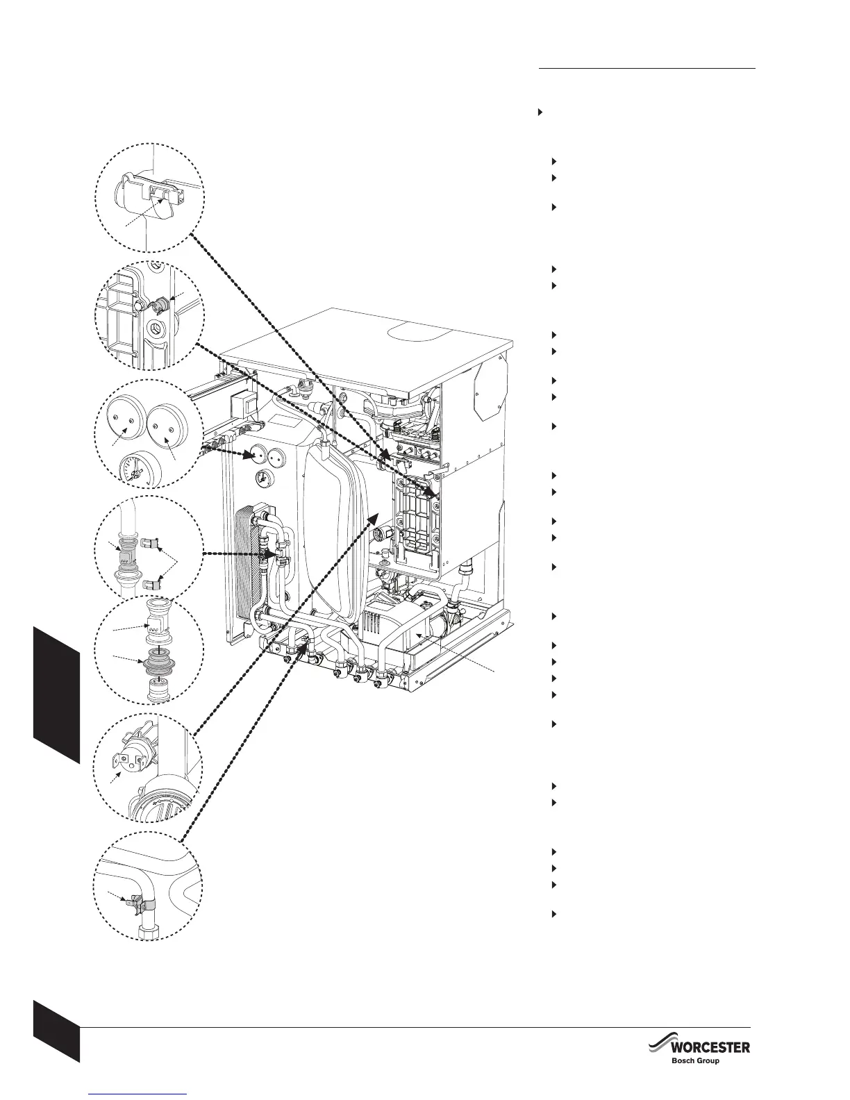
REPLACEMENT PARTS
Sensors:
Check that the appliance is electrically isolated.
Central heating flow temperature sensor (A):
Pull off the connector.
Release the sensor clip and withdraw the
sensor.
Apply heat transfer paste to the replacement
sensor.
Safety temperature limiter (B):
Pull off the connectors.
Unscrew the sensor.
Tank sensors (C):
Remove screws retaining plastic cover.
Remove cover and disconnect 2 electrical
connections.
Unscrew 2 hexagon studs.
Replace sensor coating surface with paste
supplied.
Re-assemble.
Tank overheat thermostat (D):
Remove screws retaining plastic cover.
Remove cover and disconnect 2 electrical
connections.
Unscrew 2 hexagon studs.
Replace sensor coating surface with paste
supplied.
Re-assemble.
Flow sensor/flow regulator assembly (E):
Shut off mains water at inlet valve and drain
DHW circuit.
Disconnect inline connector.
Remove 2 retaining clips (F).
Remove flow sensor assembly (E).
Remove brass housing with flow regulator (G)
from sensor.
Re-assemble ensuring that retaining clips are
correctly positioned.
Flue Temperature limiter (H):
Pull off the connector.
Unscrew the sensor.
Domestic hot water temperature sensor (J):
Release and pull-off the connector.
Unscrew the bracket.
Replace sensor coating surface with paste
supplied.
Re-assemble.
A
B
C
D
H
G
E
E
F
H
J
 Loading...