16
SYSTEM PRESSURE
Greenstar Si Compact – 6 720 807 278 (2013/05)
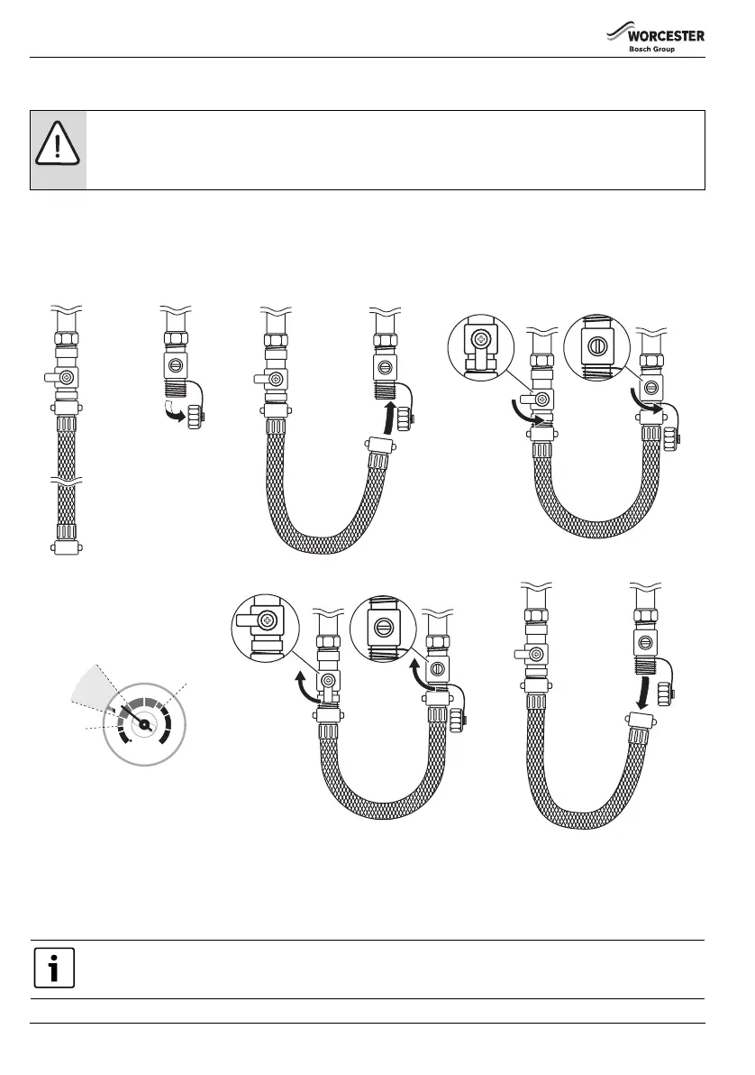
4.5 EXTERNAL FILLING LOOP
Once the external filling loop has been located, follow the instructions for re-pressurising the system.
1. Unscrew blanking cap.
2. Attach the hose to the valves, screw on hand-tight.
3. Turn the handle/screwdriver slot through 90° to open the valves.
4. The handle/screwdriver slot will be in-line with the valves
Fig. 6 External filling loop
5. When the pressure reaches between the 1 and 1.5 bar marks (zone A), turn the handle/screwdriver slot back, through 90°, to
close the valve.
6. The handle/screwdriver slot will be at 90° to the valves
7. Remove the hose and replace the blanking caps.
NOTICE: External filling loops
▶ If the filling loop does not look like the one shown in the figure below or you cannot find your filling loop, contact
your installer.
▶ To comply with Water Authority regulations you must disconnect the external filling loop after re-pressurisation.
If the pressure gauge reads more than 1.5 bar as a result of over filling, bleed one radiator until the pressure gauge
returns to between 1 and 1.5 bar.
6720643356-12.2Wo
1.
2.
7.
3.
3.
4.4.
5.
5.
6.6.
2
3
1
04
bar
 Loading...