16 17
3. With the supplied 10mm tube spanner (30) still
holding the hex head screw securely in place,
apply the at washer, spring washer, then the nut
to the top of the hex head screw and tighten in a
clockwise direction using the supplied multi-size
spanner (33) (Fig E).
4. Repeat the same process for the other 3 feet (28).
The generator can now be operated with the
generator sitting on the ground or operating
surface on the four rubber feet (28).
Portable Wheeled Type
Generator Assembly
This generator is supplied with 2 wheels to assist
with transportation, which require the following
assembly:
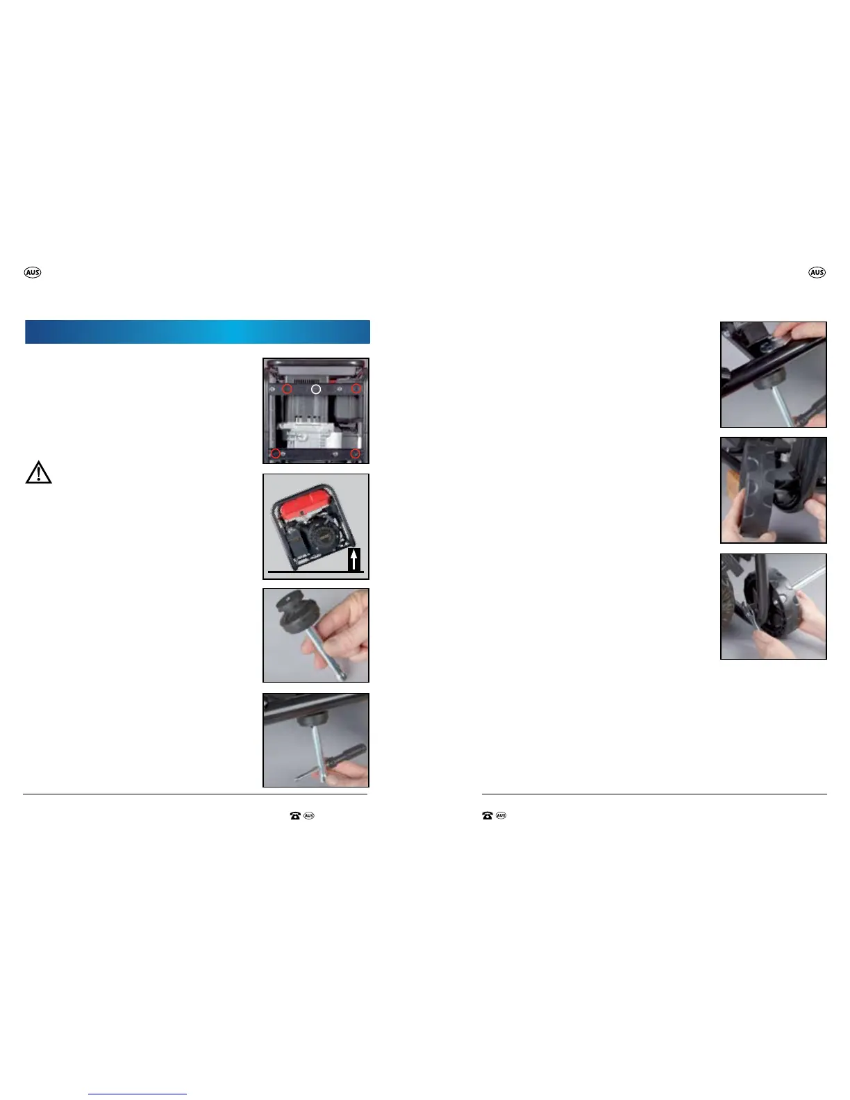
1. Remove the cover of the wheel by holding one of
the spokes of the outside cover on the wheel, and
pulling towards you until the cover disengages
and can be removed.
2. Insert the bolt through the outside of the wheel
through to the other side, then follow the bolt
through the hole in the corner frame of the
generator (Fig F).
3. Using the 21mm spark plug tube spanner (31)
to secure the bolt head in position, apply the
nut onto the end of the bolt and tighten in a
clockwise direction using the multi size spanner
(33) (Fig G). Repeat for the second wheel.
F.
G.
E.
General Assembly General Assembly
This generator has been designed to be used as
a stand alone / compact generator or a larger
portable / wheeled type generator.
Compact Stand Alone Assembly
Assembly of the Feet
NOTE: These 4 feet (28) can be tted even if the
generator will be tted with the wheeled option.
WARNING: Ensure the engine is switched
o while undertaking this task.
This generator is supplied with 4 feet (28) which
require the following assembly on the generator
(within red markers) (Fig A):
1. Place the generator on a at and level surface and
then raise one side of the generator by placing a
wooden block (or something similar) underneath
the frame (Fig B) so the generator is slightly raised
and allows you access to be able to add the
feet (28).
WARNING: Do not turn the generator upside
down or place the generator on its side. Ensure
the generator is stable and cannot topple.
2. Insert the supplied hex head screw through the
bottom of the foot so it comes out the opposite
side.
Insert the supplied 10mm tube spanner (30), into
the bottom of the foot to securely hold the hex
head screw in place, (Fig C) then place the foot
underneath the hole in the bottom frame and
push through to the upper side (Fig D).
B.
A.
Threaded wheel
foot hole
C.
D.
Assembly