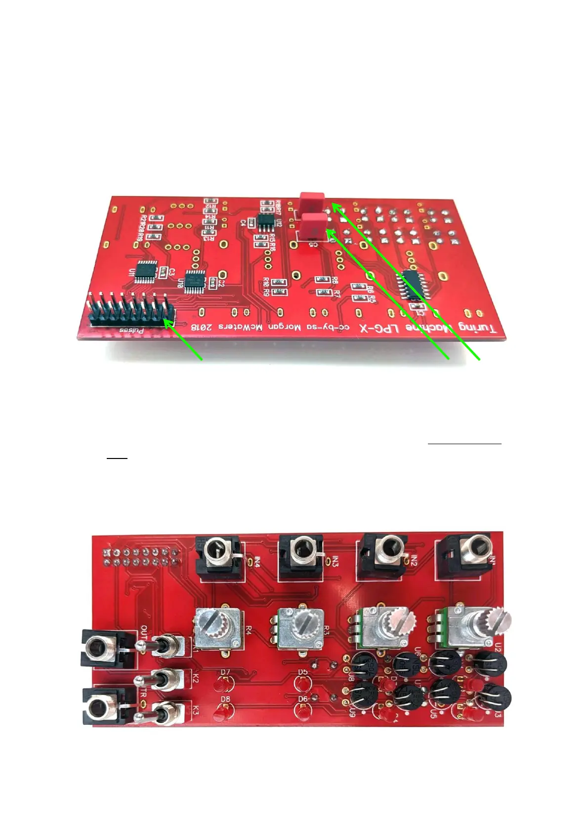
2. Next turn the PCB over and place and solder the two capacitors at C5 and C6, and
then the 2x8 male header – these parts are all placed on the opposite side of the PCB
as the vactrols. (Capacitors included in Thonk kits may look different to those in the
photo).
3. Next turn the PCB back over to the vactrol side and then place but DON’T SOLDER
YET all the front side components onto the PCB (Pots, switches, jacks, LEDs). NOTE:
The shorter leg of each LED must go towards the flat edge of the circle on the PCB
silkscreen.