2-2
Unit Description
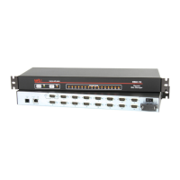
2.2. TSM Series - Back Panel
As shown in Figures 2.2, 2.3 and 2.4, the TSM Back Panel includes the following
components:
PowerInlet: An IEC-320-C14 inlet, for connection to your 100 to 240 VAC power
supply.
Notes:
• 48VDCpoweredmodelsincludeaterminalblockassembly(see
Figure4.1)inplaceofthepowerinlet.Formoreinformation,pleasereferto
Section4.1.3.
• SomeTSMseriesunitsincludeanoptional,secondaryIEC-320-C14
powerinlet.Thisallowsconnectiontoasecondarypowersourceinpower
redundancyapplications.
PowerOn/OffSwitch Master Power Switch.
Note:ThePowerOn/OffSwitchisnotpresentonTSMseriesunitsthatinclude
theoptional,secondarypowerinlet.
I
O
Ethernet 10/100 PHONE
ACT LINK
100 - 120V ~
50/60Hz 0.1-0.06A
SETUP
PORT
SERIAL PORTS
1
2
3
4
5
Figure 2.2: TSM-8 Series Units - Back Panel
I
O
Ethernet 10/100 PHONE
ACT LINK
100 - 120V ~ 50/60Hz 0.1-0.06A
1 3 5 7 9 11 13 15
10 12 14 16
17 19 21 23
18 20 22 24
8 6 4 2
SETUP
PORT
1
2
3
4
5
Figure 2.3: TSM-24 Series Units - Back Panel
I
O
Ethernet 10/100 PHONE
ACT LINK
100 - 120V ~ 50/60Hz 0.1-0.06A
1 3 5 7 9 11 13 15
10 12 14 16
9 11 13 15
10 12 14 16
17 19 21 23
18 20 22 24
17 19 21 23
18 20 22 24
8642
SETUP
PORT
1
2
3
4
5
Figure 2.4: TSM-40 Series Units - Back Panel
 Loading...