The DIQ/S 182-MOD (System 182) is a modular, multiparameter measuring system designed for online analysis, capable of connecting one or two digital WTW single or double sensors. It features an integrated power pack, three relay outputs, and a Modbus RTU/RS 485 output for integration with process control systems. Each connected sensor is automatically recognized and begins measuring immediately, displaying up to two main measured parameters (e.g., pH, D.O. content, turbidity) and two secondary parameters (e.g., temperature).
Function Description:
The system's core is the DIQ/S 182-MOD Universal Transmitter, which acts as the control and operation unit. It supports direct connection of IQ sensors, or can be expanded with MIQ modules for distributed mounting or to accommodate sensors with high power consumption.
Relay Outputs:
The three relay outputs are highly programmable and can be linked to sensors for various functions:
- Alarm Contact (Event Monitoring): Triggers a relay action (Open/Close) when a monitored event occurs, suitable for system error monitoring. Preferably configured as an opener, so that in case of power failure, the relay opens, ensuring the monitoring function remains active.
- Limit Monitor: Switches a relay when a specified limiting value (upper or lower) is exceeded or undercut. It supports monitoring with one or two relays and includes a switching delay (0-3600 s) to prevent frequent switching due to minor fluctuations.
- Proportional Output: Switches a relay cyclically on and off within a defined measured value range (proportional band). This can be configured as:
- Pulse-width output: The duration of operation (ton) corresponds to the measured value, with a constant cycle duration (T). Pulse width (v) can be set from 0% to 100%. If the measured value is at the end of the proportional range,
ton is long; if at the beginning, ton is short.
- Frequency output: The switching frequency of the output signal changes based on the measured value, with a constant switching duration (
ton = 0.3 s). Higher frequency at the end of the proportional range, lower at the beginning.
- Characteristic Curves: Proportional outputs can have positive (End value > Start value, turn-on duration/frequency increases with measured value) or negative (End value < Start value, turn-on duration/frequency decreases with measured value) characteristic curves.
- Sensor-controlled Cleaning: The relay is controlled by a linked sensor (e.g., UV/VIS sensor) to trigger a cleaning cycle. Requires a controller version from 2.80. The pulse length for cleaning can be automatic (programmed in the sensor) or set to fixed intervals (0.5 s, 1 s, 2 s, 3 s).
- Cleaning (Time-controlled): Enables automatic, time-controlled sensor cleaning using a DIQ/CHV valve module to control compressed air for a CH sensor cleaning head. The relay acts as a closer. The cleaning cycle includes a "Cleaning duration" (0-300 s) and an "Adjustment time" (0-900 s) for sensor stabilization. During cleaning, the "Clean" display flashes, and linked outputs are frozen.
- Manual Control: Allows manual opening or closing of a relay to test connected instruments.
Modbus Output:
The Modbus RTU/RS 485 output facilitates connection to a Modbus master for integration into a superordinate process control system. It transmits sensor data as a consistent 16-register data block (8 registers per sensor), including sensor number, status, model, status info, measuring mode, measured value status, main measured value, and secondary measured value. The DIQ/S 182-MOD provides data for read access only, supporting Modbus commands like Read Input Register, Read Discrete Inputs, Read Holding Register, and Read Coils.
System Configuration and Data Storage:
The system configuration, including sensor settings, relay output settings and links, Modbus settings, and system settings (language, air pressure/altitude, passwords), is permanently stored. In case of power failure, linked relay outputs switch to a non-active (open) condition, and the system automatically restarts with the last saved settings (except for the time).
Important Technical Specifications:
DIQ/S 182-MOD (Line Power Version):
- Enclosure Material: Polycarbonate with 20% glass fiber
- Weight: Approx. 0.7 kg
- Type of Protection: IP 66, Corresponds to NEMA 4X (not suitable for Conduit Connection)
- Operation Temperature: -20 °C to +55 °C (-4 to 131 °F)
- Storage Temperature: -25 °C to +65 °C (-13 to 149 °F)
- Relative Humidity (Yearly Average): ≤ 90%
- Dew Formation: Possible
- Site Altitude: Max. 2000 m above sea level
- Nominal Voltage: 100 ... 240 VAC ± 10%
- Frequency: 50/60 Hz (according to DIN IEC 60038)
- Line Power Connection: 2 pin, N and L
- Line Cross-section (Mains): Europe: 1.5 ... 4.0 mm², USA: AWG 14 ... 12
- Fuse Rating (Operator Side): Max. 16 A
- Protective Class: II
- Overvoltage Category: II
- Power Consumption: Max. approx. 12 W
- Terminals: Screw-type terminal strip (0.2-4.0 mm² solid, 0.2-2.5 mm² flexible)
- Cable Glands: Suitable for cable diameter 4.5-10 mm or 7-13 mm
- Modbus RTU/RS 485 Connection: 9-pin SUB-D socket (IP 67), compatible with Phoenix connector.
- EMC: EN 61326 (industrial areas, class B emission limits)
- System Lightning Protection: Extended protective characteristics as opposed to EN 61326
- Instrument Safety: EN 61010-1, UL 3111-1, CAN/CSA C22.2 No. 1010.1
DIQ/S 182-MOD/24V (24 V AC/DC Version):
- Nominal Voltage: 24 V AC/DC ± 10% (protective low voltage SELV)
- AC Frequency: 50/60 Hz (according to DIN IEC 60038)
- Connection: 2 pin
- Line Cross-section: Europe: 1.5 ... 4.0 mm², USA: AWG 14 ... 12
- Fuse Rating (Operator Side): Max. 16 A
- Power Consumption: Max. approx. 12 W
Relay Outputs (3x):
- Output: Galvanically separated
- Max. Switching Voltage: 240 VAC or 24 VDC
- Max. Switching Current: 2 A (AC and DC)
- Fuse Rating (Operator Side): Max. 2 A
MIQ Modules:
- Max. Number in Stack: 2 plus Universal Transmitter DIQ/S 182-MOD
- Enclosure Material: Polycarbonate with 20% glass fiber
- Weight: Approx. 0.5 kg (type-dependent)
- Type of Protection: IP 66, NEMA 4X (not suitable for conduit connection)
- SENSORNET Connections: At least two in each MIQ module
- Terminal Type: Screw-type terminal strip (0.2-4.0 mm² solid, 0.2-2.5 mm² flexible)
- Cable Glands: Suitable for cable diameter 4.5-10 mm or 7-13 mm
DIQ/JB (Branching Module):
- Enclosure Material: Polystyrene
- Weight: Approx. 0.2 kg
- Type of Protection: IP 66
- Terminals: 7 passive, potential-free terminals for line extension or branching (0.2-4.0 mm² solid, 0.2-2.5 mm² flexible)
- Cable Feeds: Prepared openings for two screwed cable glands M16 x 1.5 on upper and underside.
DIQ/CHV (Valve Module):
- Enclosure Material: Polystyrene
- Weight: Approx. 0.3 kg
- Type of Protection: IP 66
- Electrical Connections: 1x valve switching contact, 4x potential-free terminals for interface lines.
- Terminals: Screw-type terminal strip (0.2-4.0 mm² solid, 0.2-2.5 mm² flexible)
- Cable Feeds: Prepared openings for two screwed cable glands M16 x 1.5 on upper side.
- Valve Circuits: Switching voltage approx. 22 V, Max. switching current approx. 40 mA.
- Compressed Air: Required air quality: dry, free of dust and oil. Operating pressure: Max. 7x10⁵ Pa (7 bar) absolute. Connections: 6 mm hose nozzles.
Usage Features:
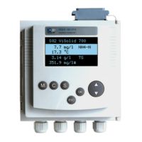
- Operating Elements: The device features a display, a toggle switch, and a keypad with dedicated keys for switching to measured value display (M), starting calibration (C), opening the SETTINGS menu (S), switching to a higher menu level or canceling entries (ESC), and opening PROPERTIES menu or confirming entries (OK). The toggle switch is used for selecting sensors, menu items, list entries, letters/numerals, and scrolling.
- Measured Value and Status Display: Offers various display options: big double display (main parameter only), detailed double display (main and secondary parameters), and single display (cyclically switches between connected sensors every 3 seconds). It also displays interface status, date, time, and relay states or Modbus communication status.
- SETTINGS Menu: Allows configuration of language, sensor settings (name, measuring mode, range), relay output parameters, Modbus interface parameters (device address, baud rate, parity), system date/time, pressure/altitude, display contrast, and resetting to delivery state.
- PROPERTIES Menu: Provides access to calibration data, system component information (type, serial number, software version), operational voltage status, communication status, current interface states, and a list of connected components. It also allows switching sensors into maintenance condition.
- Passwords: Two password levels (settings and calibration) can be assigned and activated to protect against unauthorized changes or calibration. Default passwords are set to 1000.
- Sensor Administration: Supports creating specific sensor number assignments, changing existing assignments, and creating identical assignments across multiple systems. Inactive sensor datasets (from removed sensors) are stored and can be reactivated for a substitute sensor of the same type, retaining all settings and links.
Maintenance Features:
- Maintenance Activities: IQ sensors require maintenance as per their specific operating manuals. The DIQ/S 182-MOD, DIQ modules, and MIQ modules generally require no specific maintenance.
- Cleaning: Components should be cleaned of gross contamination as necessary, especially before opening the enclosure. Enclosure surfaces and display windows can be wiped with a damp, lint-free cloth. Compressed air can be used to blow off dirt.
- Cautions for Cleaning: Avoid contact with acetone or similar cleaning agents on plastic parts. Never use high-pressure cleaners.
- Maintenance Condition: When an IQ sensor is calibrated, cleaned, serviced, or repaired, the maintenance condition should be activated. In this state, the system ignores current measured values and linked output conditions, preventing unwanted reactions. It is automatically activated during calibration and compressed-air cleaning cycles.
- Log Book: The system performs cyclical self-tests and records information or error messages in a log book. This log book provides instructions for clearing errors directly on the terminal. Error and info symbols flash in the display header to indicate new or unacknowledged messages.