Do you have a question about the wtw Turb 555 and is the answer not in the manual?
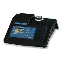
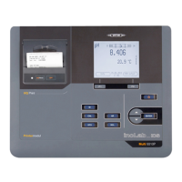
Details the function of the touch pad and its keys for instrument operation.
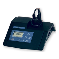
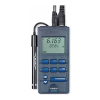
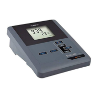
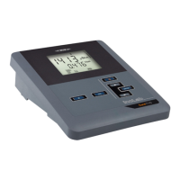
Describes the instrument's digital display and its various indications and symbols.
Identifies the location and purpose of connection sockets on the instrument.
Specifies the intended and authorized applications for the turbidity measuring instrument.
Provides essential safety guidelines for the safe operation and maintenance of the instrument.
Guides through the first-time setup and initial configuration of the instrument.
Details the procedure for correctly connecting the instrument's power supply.
Explains how to power on the instrument and the necessary warm-up period.
General instructions and best practices for operating the turbidity meter.
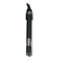
Explains how to mark and align cuvettes for precise and reproducible turbidity measurements.
Discusses methods to avoid or remove air bubbles in samples for accurate readings.
Outlines the procedures and methods for performing turbidity measurements.
Explains the instrument's measuring system, principles, and available methods.
Step-by-step guide for performing individual turbidity measurements on samples.
Details the use of the optional pour-through vessel for efficient sample measurement.
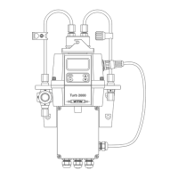
Explains the application of the flow-through vessel for continuous turbidity monitoring.
Information on security codes for protecting calibration data and instrument configuration.
Explains the purpose and types of access codes for the instrument.
Step-by-step instructions on how to input calibration or setup access codes.
Comprehensive guide to calibrating the turbidity measuring instrument for accuracy.
Explains the importance, necessity, and frequency of instrument calibration.
Outlines the available calibration methods, including five-point and user-defined.
Lists the essential preparatory steps required before performing instrument calibration.
Detailed procedure for performing a five-point calibration using standard calibration points.
Instructions for customizing the calibration process based on user-defined standards.
Guides users on adjusting instrument settings to meet specific requirements.
Overview of the instrument's setup function and the adjustable parameters.
Specific steps to modify settings like measuring unit, ratio method, and resolution.
How to restore the instrument's settings to the original factory defaults.
Information on connecting to output devices and recording measurement data.
Steps to establish a connection between the instrument and external output devices.
Explains how to transmit measured data to a printer or PC, including periodical output.
Details the information contained within the instrument's calibration record output.
Step-by-step guide for safely replacing the instrument's lamp module if it fails.
Procedures for cleaning the instrument's exterior surfaces and sample cuvettes.
Instructions on how to clean the external housing of the turbidity meter.
Detailed steps for cleaning the sample cuvettes to ensure accurate measurements.
Guidelines for the proper and legal disposal of the instrument and its components.
Troubleshooting steps for when the instrument displays a '----' error.
Guidance for resolving issues indicated by an 'Or' display message.
Actions to take when the CAL indicator on the display starts flashing.
Identifies causes and remedies for unexpectedly high turbidity readings.
Solutions for when the sample flow is obstructed in the pour-through vessel.
Addresses Warning W-01, typically related to the light source functionality.
Troubleshooting guidance for various warning messages including W-02 to W-05 and WNG.
Troubleshooting steps for Warning W-06, often indicating a calibration error.
Troubleshooting steps for Warning W-07, usually related to calibration errors.
Troubleshooting steps for Warning W-08, indicating calibration issues.
Steps to resolve instrument errors indicated by E-01 or SFE messages.
Solutions for when the instrument's keys are unresponsive.
Specifies the operational and storage temperature ranges for the instrument.
Details the specifications and requirements of the instrument's power supply.
Provides the physical dimensions and weight of the turbidity meter.
Indicates the acceptable temperature range for samples being measured.
Describes the fundamental principles and methods used for turbidity measurement.
Information on the type of light source used in the Turb 555 and Turb 555 IR models.
Lists calibration standards and spare lamp modules available for the Turb 555.
Lists calibration standards and spare lamp modules available for the Turb 555 IR.
Details general accessories like vessels, cuvettes, and cables applicable to both instrument models.
An explanation of abbreviations used throughout the operating manual and on the instrument display.
An alphabetical index to help users quickly locate specific topics or information within the manual.
| Light Source | LED |
|---|---|
| Wavelength | 860 nm |
| Protection Class | IP67 |
| Measuring Principle | Nephelometric |
| Power Supply | 4 x AA batteries |
| Display | LCD |
| Operating Temperature | 0 to 50 °C |
| Storage Temperature | -20 to 60 °C |