IBM Document: Wyse 03/97 Doc # 1335W05
Page 3 of 3 Copyright International Business Machines, 1997
All rights reserved
Error Codes Description
0 Character RAM
1 Attribute RAM
2 Font RAM
A Port 1 RTS to CTS Error
B Port 1 DTS to DSR Error
C Port 1 DTR to DCD Error
D Port 2 RTS to CTS Error
E Port 2 DTS to DSR Error
F Port 2 DTR to DCD Error
K Lost Setup (Battery Failure)
P EPROM Checksum
X Port 1 Transmit to Receive Error
Y Port 2 Transmit to Receive Error
a Parallel Port D0 to D1 (ACK) Error
b Parallel Port D2 to D3 (Busy) Error
c Parallel Port D4 to D5 (PE) Error
d Parallel Port D6 to D7 (Error) Error
LED On/Off
(Constantly)
Parallel Port STB (Strobe) Error
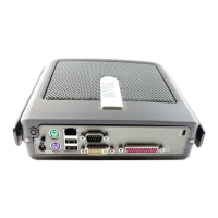
DB-25 Even Parallel Loopback Connector
Wiring
From Pin To Pin
2 10
4 11
6 12
8 15
1* 17*
*An LED is installed between pin 1 (cathode side of LED) &
pin 17 (Anode side of LED) of the DB-25 even parallel
loopback connector
DB-25 Odd Parallel Loopback Connector
Wiring
From Pin To Pin
3 10
5 11
7 12
9 15
1* 17*
*An LED is installed between pin 1 (cathode side of LED) &
pin 17 (Anode side of LED) of the DB-25 odd parallel
loopback connector
DB-25 Serial Loopback Connector Wiring
From Pin To Pin
2 3
4 5
6 8
8 20
9-Pin Loopback Connector Wiring
From Pin To Pin
1 4
2 3
4 6
6 9
7 8
Diagnostics
The Power-On diagnostic will display one of the preceding
error codes of (0-2, A-F, K, P, X, Y, a-d) if error is present.
Servicing / Repair
If any part is determined to be non functional or in failure then
the whole terminal is to be issued replaced, however, the
removal procedures are included for reference.
For certified technicians ONLY
If CRT adjustments are needed refer to the preceding
Loopback configurations and the following adjustment
parameters for the appropriate adjustment.
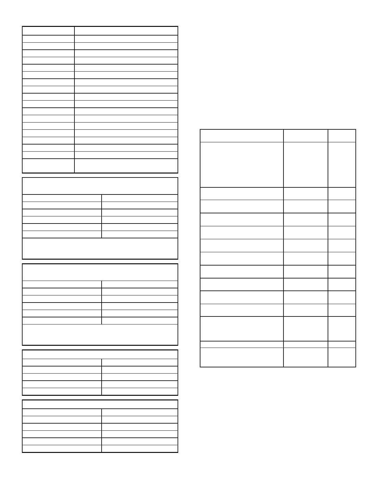
Certified Adjustments
and Specifications
Using Test
Pattern
Point to
Adjust
+30.5 VDC
+30.5 VDC ± 0.15 VDC
+15 VDC ± 0.75 VDC
+ 5 VDC ± 0.25 VDC
+ 6.3 VDC ± 0.32 VDC
- 6.3 VDC ± 0.63 VDC
“M” test
measured at:
Cathode-D113
Cathode-D110
Cathode-D109
U11 PIN 14
U11 PIN 01
VR101
Horizontal Hold
Best display stability
Mode 1 Pattern
H-sync to Grd.
VR201
Display Rotation
“square” to bezel ± 1.2mm
Mode 1 pattern Yoke
Vertical Center
Centered ≤ 5 mm
Mode 1 pattern Center
Rings
Horizontal Center
Centered ≤ 5 mm
Mode 1 pattern VR202
Vertical Size, Mode 1
172 mm ± 5 mm
Mode 1 pattern VR302
Vertical Size, Mode 2
172 mm ± 5 mm
Mode 2 pattern VR301
Vertical Size, Mode 3
172 mm ± 5 mm
Mode 3 pattern VR304
Vertical Linearity
Correct linearity (10% /better)
Mode 1 pattern VR303
Horizontal Size
237 mm ± 5 mm
Mode 1 pattern L201
Sub-Brightness
1fL (+ 0.4-0.2)
Mode 1 pattern VR204
Sub-Contrast
White 45 fL (+ 7-3)
Green 70 fL (+ 7-3)
Amber 32 fL (+ 7-3)
“M” pattern VR402
Focus - Optimum focus “M” pattern VR203
Pincushion
Least pincushion distortion
of ( ≤ 2.5 mm)
Mode 1 pattern Yoke
Magnets
 Loading...