EasyManua.ls Logo

Wyse 160 - User Manual

Wyse 160
3 pages
Print Icon
To Next Page IconTo Next Page
Loading...
Wyse Terminal
160
IBM Document: Wyse 03/97 Doc # 1335W05
Page 1 of 3 Copyright International Business Machines, 1997
All rights reserved
Wyse Terminal 160
Specifications
Model
Wyse 160
Emulation
ASCII
ANSI
Tektronix 4010/4014
Alloy PC-CGA
PC-99GT graphics w/Hercules
CGA, EGA, VGA
Standard Features
Dual session support
Two serial ports
One parallel port
Multiple display formats
Tilt/Swivel base
14 non-glare screen
Dimensions
12.7 h x 12.5 w x 12.5 d
16.53 Lb.
Power
110/220 VAC @50-60 Hz using 45 watts
Special Notes
The terminal contains High-Voltage and is extremely
dangerous. Disconnect any power cords when working
on the inside of the terminal with the cover removed.
Be careful of the CRT face. The slightest crack in the
face could cause an implosion, therefore, causing an
injury. Always work with the neck of the unit facing you.
When wearing the grounding strap do not connect it to
the terminal directly
Remember to remove your grounding strap at anytime
when the terminal is to be powered on.
The Anode lead may still contain a build-up charge after
the power has been removed so avoid touching it until
you are able to discharge it with the removal procedure.
Tools Needed
Assembly/Removal Tools Needed
Insulated #1 Phillips screwdriver
Insulated #2 Phillips screwdriver
Insulated 12 flat-blade screwdriver
Long-nose pliers
Test leads
Diagnostic Tools Needed
Digital multimeter
High voltage probe
150 MHz oscilloscope
DB-25 Even parallel loopback connector
DB-25 Odd parallel loopback connector
DB-25 Serial loopback connector
9 Pin loopback connector
Field Replacement Units
Description OEM Part IBM Part
Wy-160 14 Amber Terminal 900373-07 93F5657
Wy-160 14 Green Terminal 900373-01 93F5658
Wy-160 14 White Terminal 900373-04 93F5637
Keyboard Assembly - Ascii 840338-01 93F5659
Keyboard Assembly - Ansi 840338-09 93F5660
Enhanced PC KB Assembly 900242-01 93F5224
Wyse Keyboard 840358-01 93F5661
Question and Answer IconNeed help?

Do you have a question about the Wyse 160 and is the answer not in the manual?

Summary

Tools Needed

Assembly;Removal Tools Needed

Lists required tools for the assembly and removal of terminal components.

Diagnostic Tools Needed

Lists tools necessary for performing diagnostic tests on the terminal.

Removal Procedures

Cables and Cover Removal

Step-by-step instructions for removing the terminal's cables and outer cover.

Fuse Replacement

Procedure for safely locating and removing the fuse from the printed circuit board.

Anode Cap Discharging

Procedure for safely discharging the CRT anode cap before handling.

Operator Control Assembly

Instructions for detaching and removing the operator control assembly.

Tilt-Swivel Base Removal

Steps to remove the terminal's tilt-swivel base assembly.

Main Circuit Board Removal

Circuit Board Components

Details on disconnecting various harnesses and grounding wires from the circuit board.

CRT Assembly Removal

CRT and Bezel Handling

Procedure for removing the CRT assembly, including bezel and tube.

Yoke Removal

Yoke Adjustment

Instructions for safely removing the yoke from the CRT neck.

Diagnostics and Servicing

Error Codes

List of error codes and their corresponding descriptions for troubleshooting.

Loopback Connector Wiring

Wiring diagrams for DB-25 and 9-pin loopback connectors.

Certified Adjustments

Technical parameters and test points for CRT adjustments.

Overview

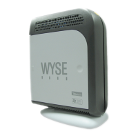
The Wyse Terminal 160 is a video display terminal designed for various computing environments, offering a range of emulations and standard features to support diverse applications. It functions as an interface for users to interact with computer systems, displaying text and graphics.

Function Description

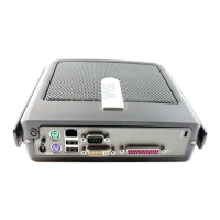
The Wyse Terminal 160 serves as a display and input device, allowing users to view information and enter commands. It supports multiple emulations, making it compatible with different host systems and software. This includes ASCII for basic text-based communication, ANSI for more advanced terminal control sequences, and Tektronix 4010/4014 for graphics applications. Additionally, it supports Alloy PC-CGA, PC-99GT graphics with Hercules, CGA, EGA, and VGA, indicating its capability to display various graphics modes common in PC environments. The terminal is designed for dual session support, enabling a user to connect to and manage two separate host sessions concurrently, which can enhance productivity in multi-tasking scenarios. It features two serial ports for connecting to host computers or other serial devices, and one parallel port, typically used for connecting printers. The tilt/swivel base allows for ergonomic adjustment of the screen, and the 14-inch non-glare screen aims to reduce reflections and eye strain for comfortable viewing over extended periods.

Important Technical Specifications

  • Model: Wyse 160
  • Emulations: ASCII, ANSI, Tektronix 4010/4014, Alloy PC-CGA, PC-99GT graphics w/Hercules, CGA, EGA, VGA
  • Standard Features: Dual session support, two serial ports, one parallel port, multiple display formats, tilt/swivel base, 14" non-glare screen.
  • Dimensions: 12.7" (h) x 12.5" (w) x 12.5" (d)
  • Weight: 16.53 Lb.
  • Power: 110/220 VAC @50-60 Hz, consuming 45 watts.
  • Certified Adjustments and Specifications (for technicians):
    • Voltage: +30.5 VDC ± 0.15 VDC, +15 VDC ± 0.75 VDC, +5 VDC ± 0.25 VDC, +6.3 VDC ± 0.32 VDC, 6.3 VDC ± 0.63 VDC.
    • Horizontal Hold: Best display stability (Mode 1 Pattern, H-sync to Grd.).
    • Display Rotation: "square" to bezel ± 1.2mm (Mode 1 pattern).
    • Vertical Center: Centered ≤ 5 mm (Mode 1 pattern).
    • Horizontal Center: Centered ≤ 5 mm (Mode 1 pattern).
    • Vertical Size (Mode 1, 2, 3): 172 mm ± 5 mm.
    • Vertical Linearity: Correct linearity (10% /better) (Mode 1 pattern).
    • Horizontal Size: 237 mm ± 5 mm (Mode 1 pattern).
    • Sub-Brightness: 1fL (+0.4/-0.2) (Mode 1 pattern).
    • Sub-Contrast: White 45 fL (+7-3), Green 70 fL (+7-3), Amber 32 fL (+7-3) ("M" pattern).
    • Focus: Optimum focus ("M" pattern).
    • Pincushion: Least pincushion distortion of (≤2.5 mm) (Mode 1 pattern).

Usage Features

The Wyse Terminal 160 is designed for ease of use and flexibility in various computing environments. Its support for multiple emulations means it can seamlessly integrate into systems requiring different terminal types, from basic ASCII to more complex graphics-capable systems. The dual session support is a key feature for users who need to access and manage information from two different sources or applications simultaneously, enhancing workflow efficiency. The inclusion of two serial ports and one parallel port provides ample connectivity options for host systems, printers, and other peripherals. The tilt/swivel base allows users to adjust the screen angle and height for optimal viewing comfort, reducing physical strain during prolonged use. The 14-inch non-glare screen is intended to minimize reflections from ambient light, improving readability and reducing eye fatigue. The terminal operates on standard 110/220 VAC power, making it suitable for deployment in various regions.

Maintenance Features

The manual provides detailed procedures for the removal and replacement of various components, indicating that the terminal is designed with some level of serviceability, primarily for certified technicians.

Special Notes for Maintenance:

  • High Voltage Warning: The terminal contains high voltage and is extremely dangerous. All power cords must be disconnected when working inside the terminal with the cover removed.
  • CRT Safety: The CRT face is fragile; a slight crack can cause an implosion, leading to injury. Always work with the neck of the unit facing you.
  • Grounding Strap: Do not connect the grounding strap directly to the terminal. Remember to remove the grounding strap when the terminal is to be powered on.
  • Anode Lead Charge: The Anode lead may retain a charge even after power is removed. Avoid touching it until it has been discharged using the specified procedure.

Tools Needed for Assembly/Removal:

  • Insulated #1 Phillips screwdriver
  • Insulated #2 Phillips screwdriver
  • Insulated 12" flat-blade screwdriver
  • Long-nose pliers
  • Test leads

Diagnostic Tools Needed:

  • Digital multimeter
  • High voltage probe
  • 150 MHz oscilloscope
  • DB-25 Even parallel loopback connector
  • DB-25 Odd parallel loopback connector
  • DB-25 Serial loopback connector
  • 9 Pin loopback connector

Removal Procedures (for certified technicians):

  • Cables and Cover: Involves disconnecting power and other cables, removing screws from the operator control panel and the back of the terminal, and sliding the cover off.
  • Fuse: Located on the printed circuit board behind the AC power plug, removed by hand or pliers.
  • Anode Cap Discharging: A critical safety step involving grounding a screwdriver to the terminal's metal frame and touching the spring clips inside the anode cap to discharge the CRT, then removing the cap with pliers.
  • Operator Control Assembly: Involves removing various harness connections (Contrast, Power switch, Brightness, LED, Yoke, Keyboard), unplugging the CRT harness, unscrewing ground wires, and removing clamp-downs.
  • Tilt-Swivel Base: Involves placing the CRT face on a padded surface, removing screws from the back of the swivel base, and sliding the base off.
  • Main Circuit Board: Requires discharging the Anode Cap, cutting/removing a strap, removing screws, disconnecting multiple harnesses (Contrast, Power switch, Brightness, LED, Yoke, Keyboard), unplugging the CRT harness, unscrewing ground wires, removing clamp-downs, and sliding the board out.
  • CRT Assembly: Involves discharging the Anode Cap, removing the Operator Control Assembly, removing bezel screws, ensuring no remaining cables, removing the case from the bezel and CRT, removing bezel screws from the CRT tube, and lifting the CRT to slide the bezel out.
  • Yoke: Requires removing the Yoke harness, loosening a thumbscrew on the CRT neck, and carefully sliding the Yoke off.

Error Codes and Diagnostics:

The terminal displays error codes (0-2, A-F, K, P, X, Y, a-d) during power-on diagnostics to indicate specific failures such as Character RAM, Attribute RAM, Font RAM errors, serial port errors (RTS, DTS, DTR to CTS, DSR, DCD), Lost Setup (Battery Failure), EPROM Checksum, parallel port errors (D0-D1 ACK, D2-D3 Busy, D4-D5 PE, D6-D7 Error, STB Strobe), and LED On/Off issues. While the manual states that a non-functional part should be replaced, the detailed removal procedures and diagnostic adjustments (using loopback connectors and specific test patterns) are provided for certified technicians to troubleshoot and adjust CRT parameters like horizontal/vertical hold, size, linearity, brightness, contrast, focus, and pincushion. Field Replacement Units (FRUs) are listed with OEM and IBM part numbers for various components, including different terminal configurations (Amber, Green, White), and keyboard assemblies (ASCII, ANSI, Enhanced PC KB, Wyse).

Wyse 160 Specifications

General IconGeneral
BrandWyse
Model160
CategoryServer
LanguageEnglish

Related product manuals