©2000 Xantrex Technology Inc.
3.0 INSTALLATION
Diversion Control Mode Cabling
When using the C-Series unit as a diversion or DC load controller, the DC
load needs to be connected to the controller terminals marked as PV POS/LOAD
and COMMON NEGATIVE. The common negatives can be reversed or wired
with an appropriately sized single conductor to a more convenient location
such as a DC load center negative bus.
· Connect your DC current source (PV, wind, hydro, etc.) directly to
abattery.
· Connect an appropriately-sized cable from the positive battery terminal to
the controller terminal marked BAT POS.
· Connect a cable from the negative battery terminal to the terminal marked
COMMON NEGATIVES on the controllers circuit board.
· Connect a cable from the controllers terminal marked PV POS/LOAD to the
positive terminal of your DC diversion load.
· Connect a cable from the controllers terminal marked COMMON NEGA-
TIVES to the negative terminal of your DC diversion load.
· Tighten the terminal lugs to 20 inch-pounds for #14-10 AWG (25 for
#8 AWG, 35 for #6 AWG). Allow a little slack on the cables within the
controller and secure the wiring with strain reliefs.
NOTE: Do not use light bulbs for diversion loads. Use only resistive loads such
as air- or water-cooled heating elements.
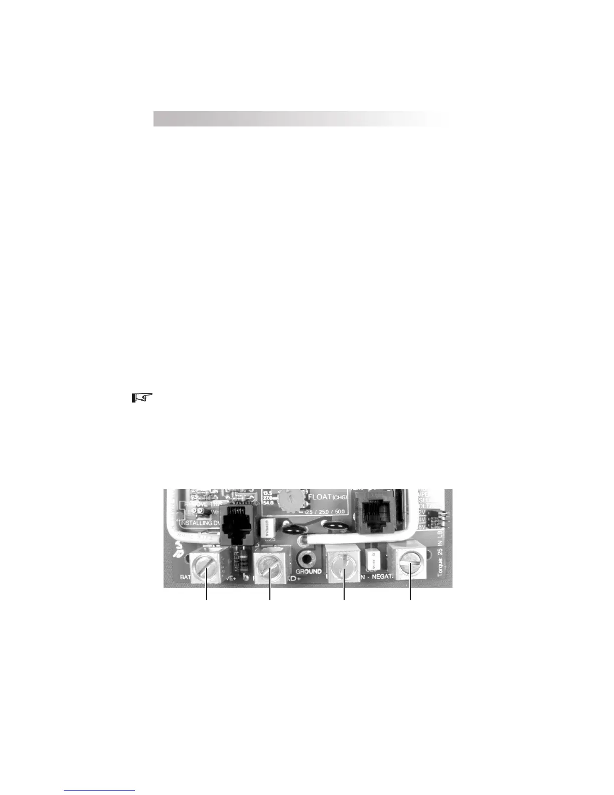
Battery Positive + Battery Negative Diversion Load
Positive +
Diversion Load
Negative
Figure 7
PV Load Diversion Wiring
18
 Loading...