©2000 Xantrex Technology Inc.
Wiring
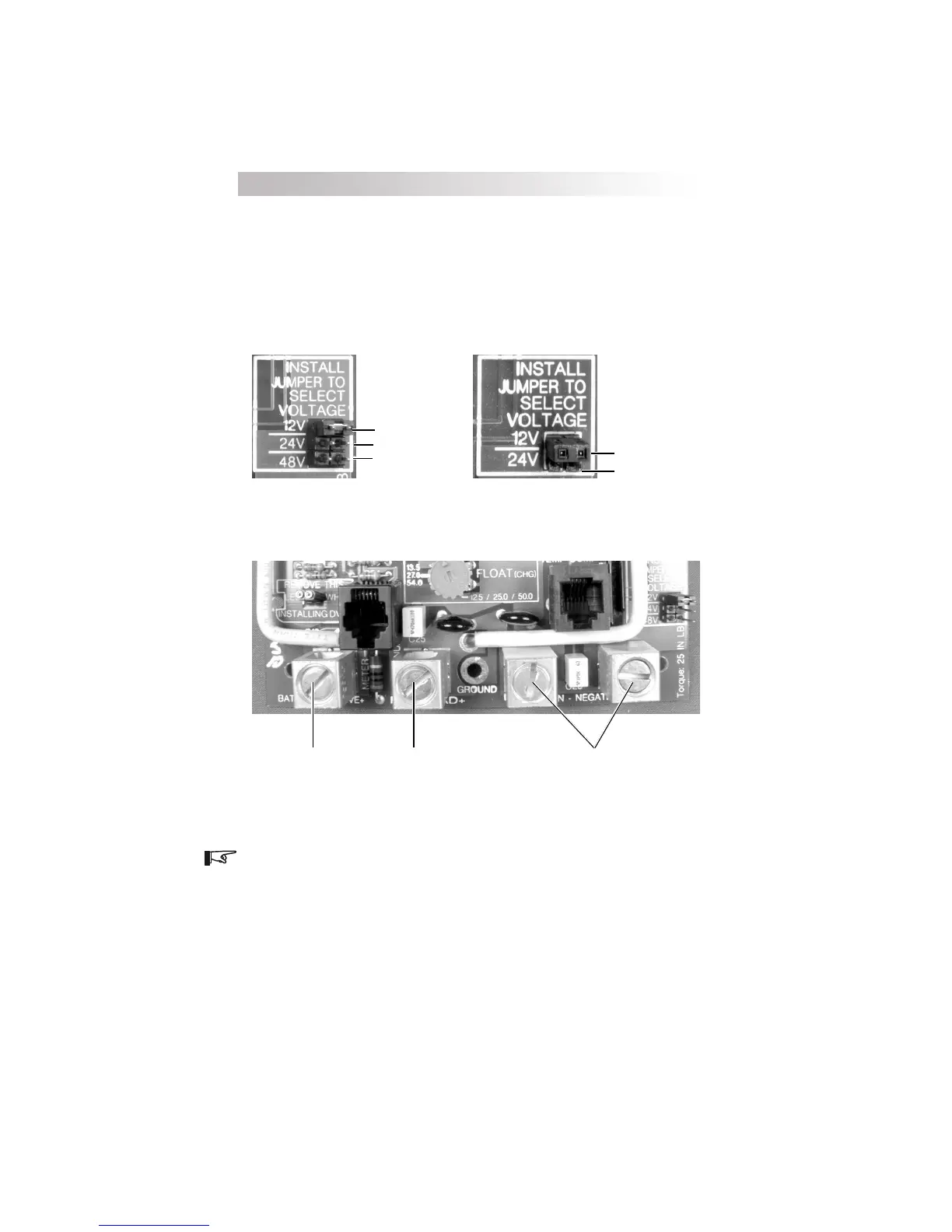
Disconnect battery and PV sources before wiring. Set the voltage
selection jumper to the appropriate setting before energizing the system (see
User Configuration Options for instructions). Incorrect settings may result in
damage to the system as charging regulation will not occur. Torque the
terminals to 20 inch-pounds for 14-10 AWG (25 for 8 AWG, 35 for 6 AWG) once
the wires have been installed. Replace the cover.
3.0 INSTALLATION
12
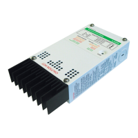
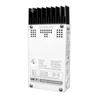
Figure 3
Voltage Selection Jumper
Battery Positive + PV +/Load +
Common Negatives
Figure 4
Battery Connection Terminals
NOTE: Regardless of configuration, only the positive conductor from a PV array
OR a DC load may be connected to the terminal marked PV POS/LOAD.
12 Volt Position
24 Volt Position
12 Volt Position
24 Volt Position
48 Volt Position
(C40 only)
C40 C35 and C60
 Loading...