6 Xanbus System Control Panel (SCP) Owner’s Guide
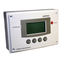
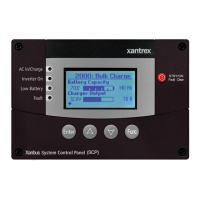
Mechanical Features
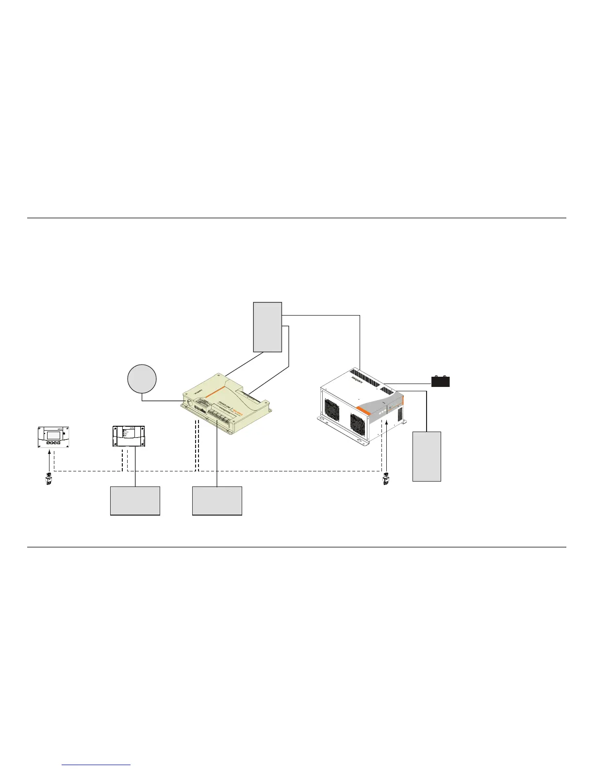
System Components
The Xanbus system includes the SCP and other Xanbus-enabled devices.
Each device interacts and communicates with the other devices.
In Figure 3, network connections are represented by dotted lines and
conventional electrical connections are represented by solid lines.
Figure 3
Sample Network Diagram
Xanbus System Control Panel
Xanbus Automatic Generator Start
System Control Panel
network terminator network terminator
Automatic Generator Start
Freedom Sequence
Freedom SW Inverter/Charger
FREEDOM SW 3012
FREEDOM SW 3012
I
nv
e
r
t
er
Reset Enable
I
nve
r
ter A
C/
On
C
ha
r
ge Fault
Generator
Shore
Power
AC Loads
AC Panel
BATTERY
Inverter
Load Panel
 Loading...