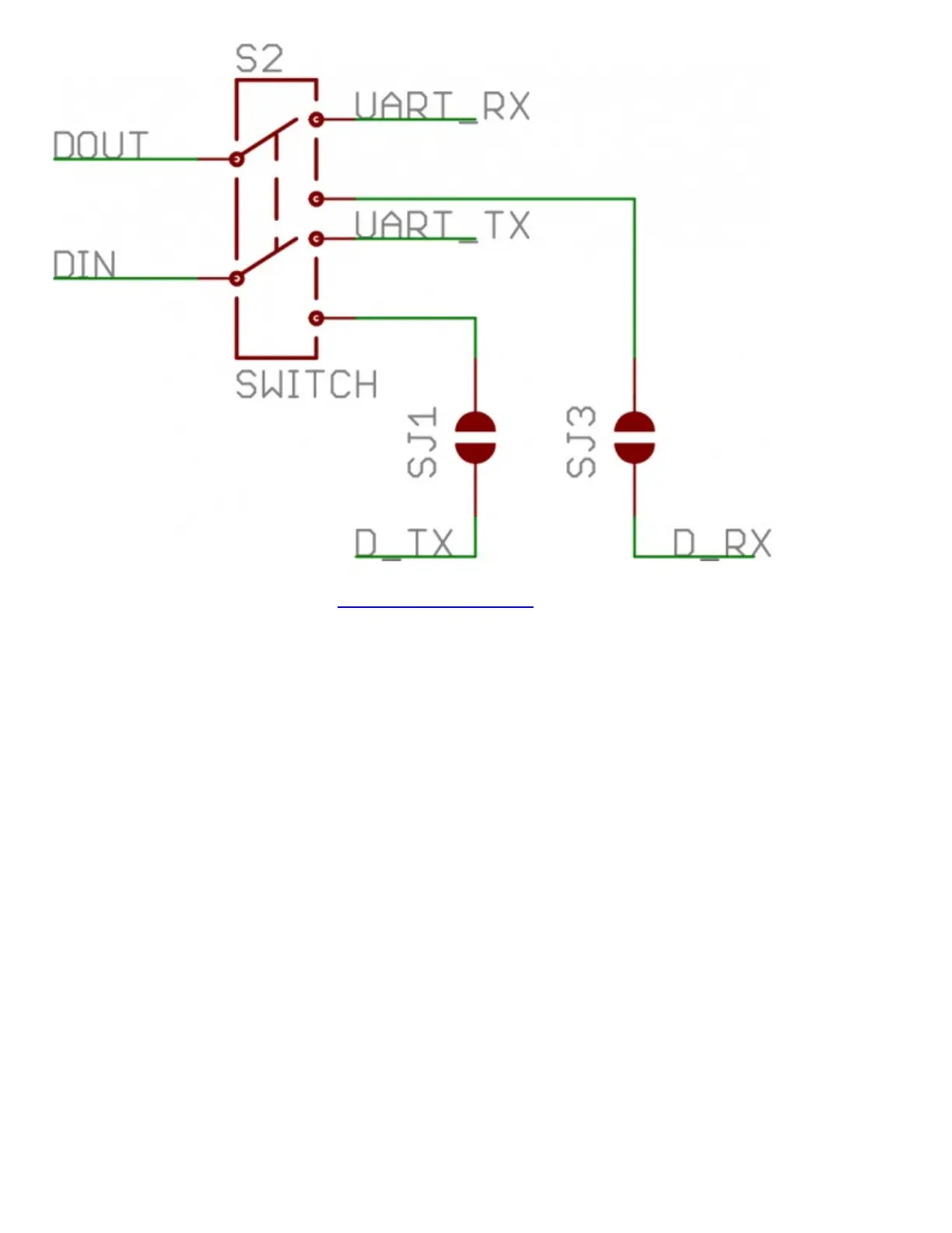
The switch configuration from the XBee Shield schematic. "D_TX" connects to Arduino pin 3, and
"D_RX" connects to Arduino pin 2.
For all of our example sketches we'll assume the switch is in the DLINE position. At the very least,
make sure the switch is in the "DLINE" position when uploading sketches.
Status LED Indicators
There are 5 LEDs on the XBee Shield. Each of these LEDs connects to a pin on the XBee, which
does most of the LED driving. Here's a table explaining the operation of each LED:
LED
Label
LED
Color
XBee Pin
Connection
Default Operation Notes
PWR Red 3.3V Indicates power is present.
DIO5 Green Associate/DIO5
Associated indicator -- blinks when the XBee is associated
with another XBee.
DOUT Red DOUT Indicates wireless data is being received.
DIN Green DIN Indicates wireless data is being transmitted.
RSSI Green PWM0/RSSI
Indicates relative signal strength (RSSI) of last received
transmission.
These LEDs can be very useful for debugging. The DIO5/Associate indicator should blink when the
XBee is paired with a compatible device. The RSSI LED is actually PWM'd so it will be brighter