Xenex Disinfection Services LLC- Confidential and Proprietary Information.
12082017 Original Instructions. 730-00009-02
xenex.com | 866-867-9799 | page 3
PODSETUP
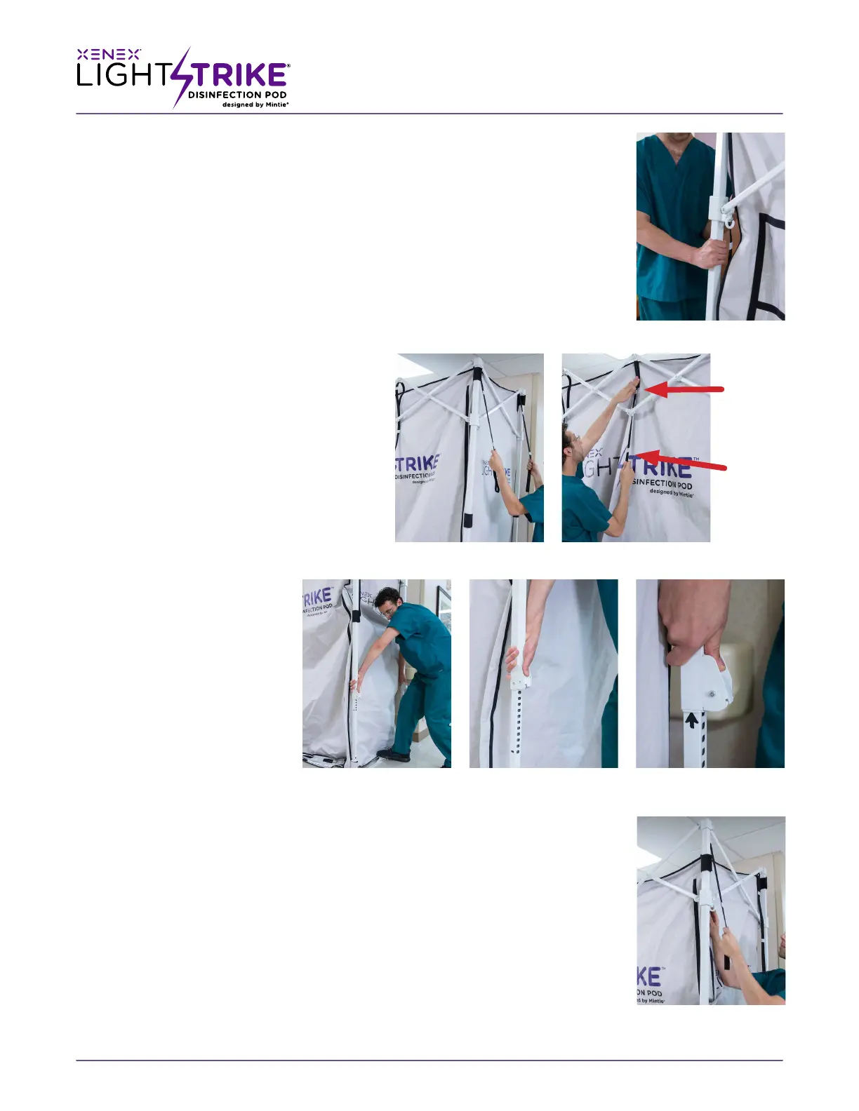
5. At each corner, push up on diagonal truss while pushing down on frame corner
supports until an audible click is heard.
(Fig1-E)
Careful: PINCH HAZARD
Repeat this step on the remaining three corner posts, this will lock the frame into it’s fully
extended footprint.
NOTE: Take caution to keep your hand away from the locking corners as they slide up
the post to their locking position to avoid pinching fingers.
Set Up: Adjusting the frame height for regular use
STANDARDFRAMESETTING
NOTE: The LightStrike™ Disinfection Pod has
two designated height positions to allow for
loading taller equipment for disinfection. Out
of the box the pod’s 8 upper support straps are
set for the standard height setting, requiring
that only the frame is adjusted.
(Fig: 2-A&B) The
standard setting allows the cargo door of the
pod to open to a usable height of 77 inches (6 ,
5 in / 1.96 meters).
6. Stand facing either end of the Pod and
place one foot on the center push plate of
the lower truss in front of you. Grip your
hands around the corner
posts and li corner posts.
Do not raise too high on
one end before raising
opposite end. You will hear
an audible click at about
18”.
(Fig: 2-C) Repeat step on
the opposite end.
7. Keep foot on center
push plate of lower
truss, depress the height
adjustment buttons and
li corners to standard
operating height. The lock
point is indicated by the black arrows that are revealed on the inside and outside of
the posts as you raise them. Repeat step on the opposite end.
(Fig: 2 -D&E)
Set Up: Adjusting the frame height for tall item use
TALLFRAMESETTINGOPTIONAL
For the taller frame setting, both the upper support straps and the frame will be adjusted
starting with the upper straps.
8. Release the 8, black upper support straps and move the second indicator tab up to the
position where the standard tab was fastened. This allows the longer black straps to
manage the envelope in the taller setting.
(Fig: 2F)
(Fig: 1E)
(Fig: 2C) (Fig:2D) (Fig: 2E)
(Fig: 2A) (Fig: 2B)
Standard
Setting
Indicator
Tall Setting
Indicator
(Fig: 2F)
 Loading...