V5 series inverter
79
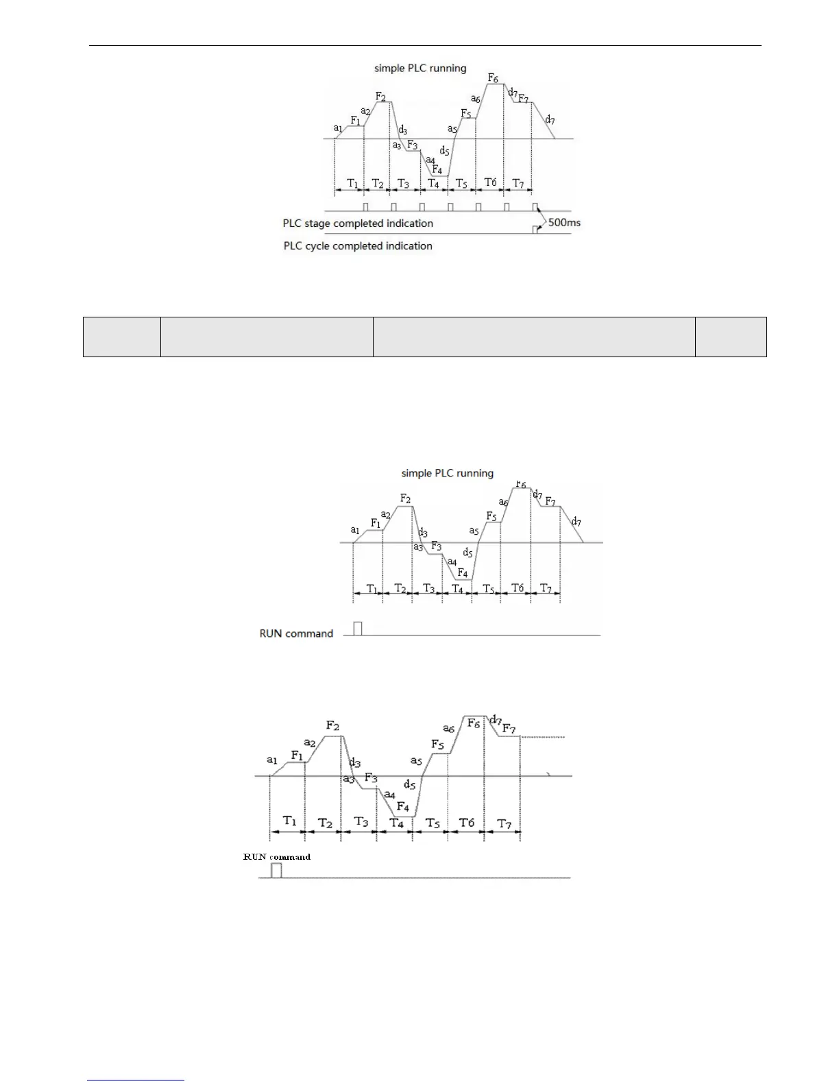
Fig.4-40 Simple PLC running
In Fig 4-40, a
1
~a
7
, d
1
~d
7
are the Acc/Dec time of each stage and they are set by Acc/Dec time parameters P0.17, P0.18 and
P3.14~P3.2. F
1
~F
7
, T
1
~T
7
are the running frequency and running time and they are set by P8.01~P8.14.
P8.00 Simple PLC running
Range: LED lowest bit: 0~3; ten bit: 0, 1; hundred bit: 0, 1;
Thousand bit: 0, 1.
0000
Lowest bit of LED: PLC running mode selection
0: Disabled. PLC running mode is invalid.
1: Stop after one cycle. As shown in Fig.4-41. If inverter stops after single cycle operation, running command should be
input once again to start the inverter.
Fig. 4-41 PLC stop mode after single cycle
2: Keep the final value after single cycle. As shown in Fig.4-42,Inverter will keep the running frequency, direction of the
last stage after single cycle is completed, then it will stop in dec time if stop command is input.
Fig. 4-42 PLC holding mode after single cycle