Do you have a question about the Xinje XP-18 Series and is the answer not in the manual?
Introduction to the XP/XMP-18 series integral industrial controller.
Follow precautions to prevent system errors, abnormal operation, or damage.
Use according to manual and recommended peripherals for normal operation.
Details manual's guide on product usage, characteristics, and programming.
Identifies intended users and the scope of the manual for XP/XMP series.
Lists available documents like User CD and Xinje website for additional information.
Lists general attention points for safe operation and handling.
Highlights critical warnings related to electrical shock, voltage, and environment.
Integrates HMI and PLC, listing key features like inputs/outputs and LCD.
Details available types for XMP and XP series based on output configuration.
Explains the components and meaning of the product type naming convention.
Covers power supply, voltage, temperature, and environment specifications.
Describes panel dimensions, download port, and communication port specifications.
Details HMI screen, display, useful life, contrast, character, and touch mode.
Lists PLC specs including executing format, speed, capacity, I/O, timers, and counters.
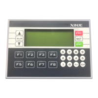
Identifies key components like screen area, function keys, and number keys on the device.
Illustrates the arrangement of input and output terminals with power and communication connections.
Describes the RS-232 program port for downloading PLC and HMI programs.
Provides the physical dimensions of the XP/XMP unit.
Explains the RS-485 communication port and its use for connecting devices.
Specifies the required dimensions for panel installation.
Details input voltage, current, response time, and signal format.
Shows how to connect input points, including sensor requirements.
Explains input loop insulation, filtering, and sensitivity requirements.
Illustrates a common connection example for input points.
Details output type, power, insulation, load capacity, and response time.
Explains output points, insulation, action indication, and response time for relay outputs.
Shows connection examples for DC and AC loads, advising on diodes and surge absorbers.
Specifies parameters for high-speed pulse output types, including frequency.
Details specs for normal transistor output, including load capacity and response time.
Illustrates the circuit for transistor outputs, including protection fuses.
Explains per-point and total current limits for transistor outputs.
Outlines instruction types for XP/XMP series, aligning with XC series PLCs.
Details special function instructions for XP2/XMP2 and XP3/XMP3, including high-speed count.
Specifies pulse outputs, interrupt channels, and frequency measurement points.
Introduces the distribution list for soft component IDs in XP/XMP series.
Details input/output points and auxiliary relay ranges for XP1/XMP1.
Lists ranges for timers, counters, and data/flash ROM registers for XP1/XMP1.
Details input/output points and auxiliary relay ranges for XP2/XMP2.
Details input/output points and auxiliary relay ranges for XP3/XMP3.
Lists ranges for timers, counters, and data/flash ROM registers for XP2/XMP2/XP3/XMP3.
Details power failure memory area settings for D, M, T, C, S components in XP1/XMP1.
Details power failure memory area settings for D, M, T, C, S components in XP2/XMP2.
Details power failure memory area settings for D, M, T components in XP3/XMP3.
Introduces XCPPro software for PLC program editing and its interface.
Guides on initiating a new project and selecting the PLC model within the software.
Refers to the XC Series Edit Tool XCP Pro User Manual for program compiling.
Shows a basic ladder logic example with internal relays and outputs.
Details how to connect the PC to the PLC and configure serial port settings.
Explains selecting serial port, baud rate, and parity for successful communication.
Describes the process of downloading the PLC program and running it.
Explains how to retrieve the PLC program from the XP/XMP to the PC.
Introduces Modbus and free format communication protocols supported by XP/XMP.
Explains the RS-485 port signals (A, B) and its use for device communication.
Lists Modbus and free format communication parameters and their default settings.
Describes how to set communication parameters and the necessity of rebooting.
Details register settings for communication mode, format, and free format.
Specifies bit assignments for baud rate, data bits, and stop bits in FD8221.
Explains bit settings for start/end symbols and communication bits in FD8226.
Explains master and slave modes for Modbus communication.
Corresponds internal soft unit numbers to Modbus addresses for coils and registers.
Details Modbus addresses for bit component addresses (M, X, Y, S).
Details Modbus addresses for word component addresses (D, TD, CD, FD).
Describes free format data transfer using data blocks, start/end symbols.
Explains the functions of keys like ESC, SET, ENT, ALM, CLR, +/-, and number keys.
Notes that keys can be defined for functions like force ON/OFF, reverse, or momentary ON.
Introduces OP20 software for editing HMI screens and its interface.
Shows how to assign functions to specific HMI keys.
Guides on starting a new project and selecting the correct XP/XMP model.
Explains how to select the integrated PLC type (Xinje XC) for communication.
Describes entering screen editing mode after initial project setup.
Details how to select the correct COM port for screen downloading.
Explains connecting the XP/XMP and PC to download the screen program.
Lists available BD board types and their functions like analog input and temperature measurement.
Provides detailed specs for the XP3-2AD2PT-BD board including voltage, temperature, and precision.
Details specs for the XP3-2TC-P-BD board for thermocouple measurement.
Details specs for the XP3-2PT2AD1DA-BD board for PT100 and analog I/O.
Illustrates input/output characteristics and insulation for BD boards.
Shows where to install the BD board on the XP3/XMP3 unit.
Lists MA model types and their capabilities like digital/analog I/O and thermocouple control.
Details specifications for MA models with digital input/output.
Provides specs for MA models with analog output and analog input.
Details specs for MA models with analog input and dual analog I/O.
Details specs for MA thermocouple and PT100 temperature modules.
Illustrates how to connect MA models via RS-485.
Explains extending with other RS-485/Modbus devices like meters and inverters.
Specifies the bus mode connection sequence and restrictions.
| Brand | Xinje |
|---|---|
| Model | XP-18 Series |
| Category | Controller |
| Language | English |