page 2 to 2
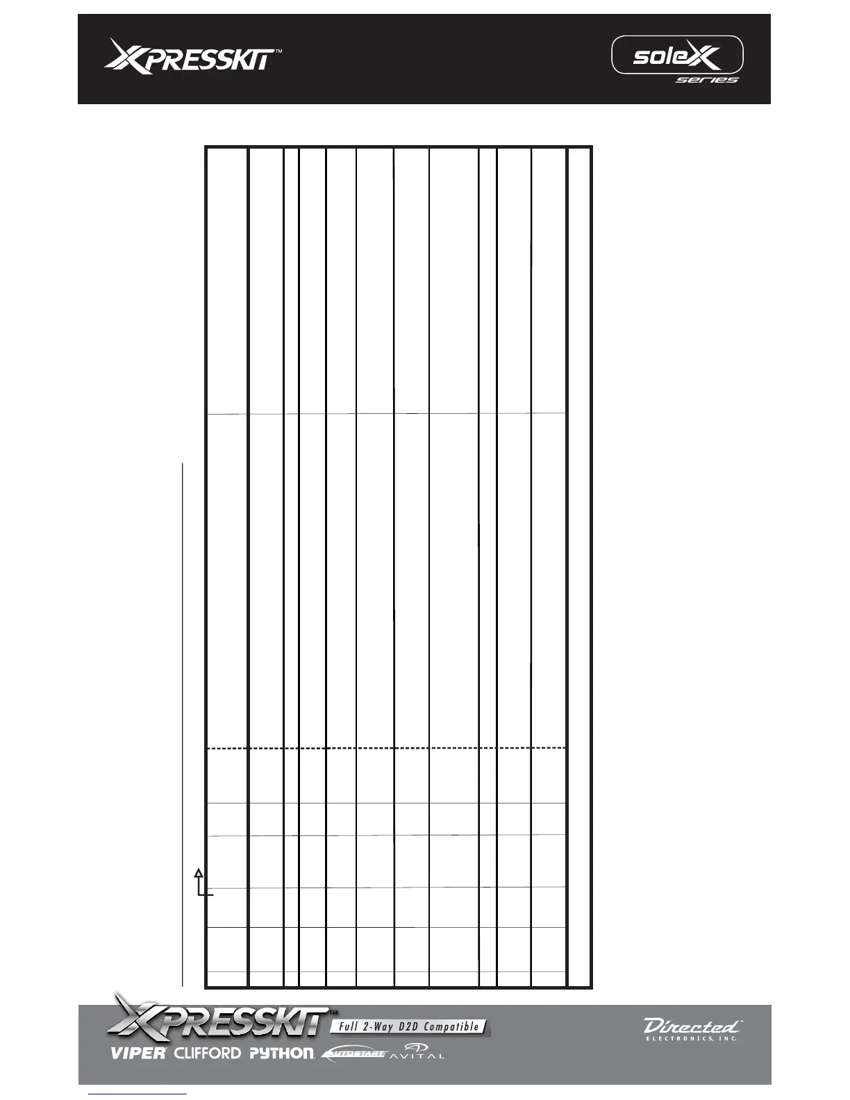
Legend RCS = Remote Control System N/C = No Connection N/A = Not Applicable W2W= analogue wire to wire D2D= data 2 data
N/C
N/C N/C
N/C
N/C N/C
Section B
(-)
/(+)
(-)
Input
Input
Input
Data
I/O
STATUS
WIRE
COLOR
Brown
Green
Blue
Violet/
White
Violet
Pink/
White
Pink
Orange
Red
Black
(-)
(+)
SPECIFIC WIRE CONNECTION LOCATION
Constant (+) 12 Volt Source
Chassis Ground
Connect
Location
Vehicle
Vehicle
Vehicle
ACTIVATION and/or FUNCTIONALITY
RCS
Power Source
Ground Source
INSTALL “A”: WIRE GUIDE: CONNECTIONS
Data Commands from Module to Vehicle
PIN#
1
2
3
4
5
6
7
8
9
10
Ground When Running (status) Output of RCS
10 PIN HARNESS
D2D
w2w
D2D = Optional use of 4 Pin Data to Data (D2D) cable will replace the analogue wire (w2w) connection
D2D
w2w
w2w
D2D
w2w
D2D
w2w
Ignition Input Source
Ignition Input Source
Vehicle
(+)
Input
w2w
Immobilizer Bypass Via Data
N/C
N/C
N/C
N/C
N/C
N/C
N/C
N/C N/C
N/C
N/C N/C
w2w
Output
(+)
Vehicle
Security Light Power Source Supply
Connect to vehicle Data wire PIN 2
See Vehicle Wiring Reference Chart for wire colors
(+)
Vehicle
w2w
Connect to vehicle security light wire PIN 5 (Key Side)
(See Vehicle Wiring Reference Chart for wire colors)
Connect to vehicle security light wire PIN 5 (ECM Side)
(See Vehicle Wiring Reference Chart for wire colors)
Security Light Power Source Return
Input
MODEL: PKH34
Rev.: 20110106
© 2008 Directed Electronics. All rights reserved.