Page 7
Please make sure to read through the separate Brushless Speed Controller User Manual included to learn more about the ESC's
features and proper use. For throttle control range calibration and programming options, see page 11.
Shock Absorber: Each shock is oil-lled and uses a spring that is well suited for most off-road conditions. The shocks are threaded
and feature preload tension rings that allow the shocks to be easily tuned for different driving conditions. The shocks come standard
with 30Wt oil and 1.5mm white springs.
Shock Tower: Secures the shock absorber while allowing many different geometry settings to suit different track conditions. The shock
towers are made from 4mm 6061 aluminium for strength.
Side Guard: Helps prevent track debris from entering and damaging transmission components and protects the battery pack from impacts.
Steering Servo: Controls the X-Terminator 2e's steering. A 'servo saver' is used to help prevent the servo gears from being stripped out.
Steering Tie-Rod: The steering tie-rod connects the steering linkage and the castor block. The tie-rods are adjustable so you can make
toe-angle adjustments to the front wheels.
Suspension Arm: Helps support the X-Terminator 2e’s handling (when coupled to shock absorbers) and braking whilst ensuring
maximum traction (keeps the wheels in contact with the ground) and protects the chassis components from undue stress and strain.
Turnbuckle: Joins the upper inner and upper outer suspension components. The turnbuckle is threaded, allowing you to adjust the
camber angle of the front and rear tyres.
Wheel/Tyre Assembly: The X-Terminator 2e features moulded rubber tyres with an aggressive tread pattern that is good for most
off-road applications. The wheels are moulded in one piece from lightweight, high-impact plastic for strength.
Wing: Provides downforce to ensure maximum traction when racing. Wing angle can be adjusted to suit different track conditions.
n
Chassis Component Overview, Continued....
BECOmING FAmILIAR WITh YOUR x-TERmINATOR 2e
n
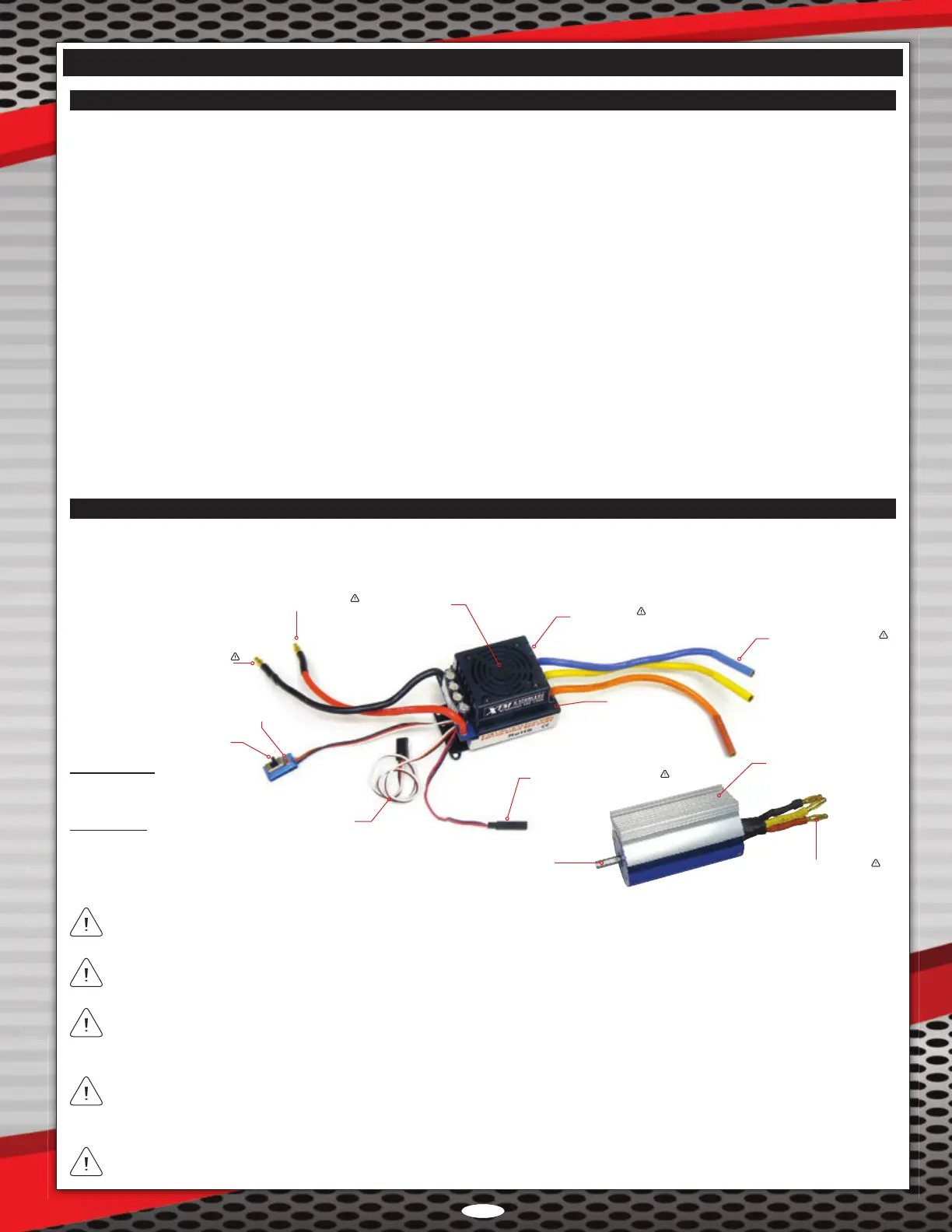
Brushless Power System Overview
The motor used in the X-Terminator 2e is a sensorless brushless motor. Therefore, the Sensor input on the ESC is not utilised. The
motor leads from the ESC can be plugged into any of the motor leads from the motor without issue. If the motor runs backwards,
swap two of the motor leads and the motor will run in the correct direction (counter-clockwise).
The Accessory Fan Connector is used to connect the optional brushless motor heat-sink with cooling fans (P/N 149862). It is NOT
recommended to use it to power any other types of accessories.
The ESC battery leads feature male battery connectors on both the positive and the negative leads. This allows plug-and-play
compatibility with most hard-case Li-Po car battery packs and allows easy dual battery pack wiring with the use of one simple
adapter. For more information, see page 9.
In the default conguration the transmitter's throttle channel servo reversing function should be set to REV (Reverse) and the motor
leads should be connected as follows: (A) Blue to motor Black, (B) Yellow to motor Red, and (C) Orange to Motor Yellow.
The Set Button is used during throttle control range calibration. For more information, see page 11.
Cooling FanPositive Battery Lead (Red)
Negative Battery Lead (Black)
On/Off Switch
Set Button
ESC Throttle Lead
Accessory Fan Connector
Motor Leads (A, B, C)
Sensor Input
Motor Shaft
Heat-Sink
Status LED
Brushless Motor
kV Rating: 2370kV
Shaft Diamteter: 5mm Shaft for 1/8th Scale Pinions
Brushless ESC
Nominal Input Voltage Range: 7.2V ~ 14.8V (6 ~ 12C Ni-Cd or Ni-MH / 2 ~ 4S Li-Po)
Output Rating: 120 Amps
BEC: Switch Mode 3A/6V
Programmable: Yes
Motor Leads (A, B, C)