5
INSTALLATION
After unpacking the fridge/freezer check that no
parts are missing. Place the unit in a dry place which
is protected against splashing water. Do not place
directly adjacent to sources of heat such as heating,
gas ovens, hot water, pipes or directly in the sun.
It is important that your appliance is installed and
operated in accordance with these instructions to
ensure its performance, efficiency and operation.
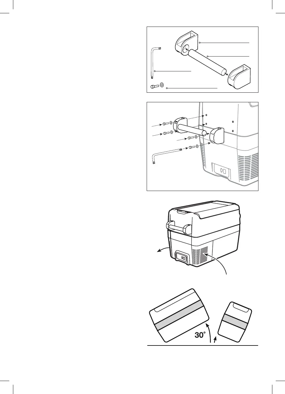
ASSEMBLY
To Assemble the handles
1 Insert one handle tube into two handle ends
(Fig. 1)
2 Attach the assembled handle to the fridge using
the screws and washers (4) with the Allen key
provided. (Fig. 2)
3 Repeat on the other end.
APPLICATION AND OPERATIVE
COOLING RANGE
The cooling compartment has varying temperature
zones. The values indicated on the digital display are
related to the middle of the cabinet. The Single Zone
Fridge/Freezer is designed to either refrigerate
or freeze food. The fridge/freezer may be used
for outdoor use such as for camping purposes. If
you wish to refrigerate medicines, first check to
ensure the fridge/freezer’s cooling capacity meets
the demands of the respective medicines. The
fridge/freezer is designed to operate in ambient
temperatures between -10° and +55° C in a
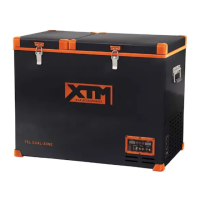
maximum air humidity of 90%. The fridge/ freezer
can operate continuously at a maximum angle of
30°. Level operation is preferable.
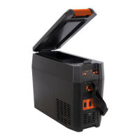
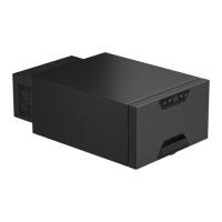
NOTE: The normal operation of the appliance
requires heat to be radiated away from the
condenser located at the end of the cabinet.
Adequate airflow is required around the compressor
at all times. (Fig. 3).
The cooling system has been designed to operate
correctly when the appliance is positioned on angles
up to 30 degrees. It is recommended that the time
the unit is exposed to angles over 30 degrees is
limited to a maximum of four (4) hours continuous
operation. (Fig. 4).
HANDLE ENDS x 4
HANDLE TUBE x 2
SCREW & WASHER x 8
ALLEN KEY x 1
FIG. 4
FIG. 3
FIG. 1
FIG. 2
Air Flow