VESDA by Xtralis
VESDA VFT Product Guide
www.xtralis.com 13
Detector Access
To gain access to the interior of the detector, first disconnect the power supply then remove the front cover. It
is secured by two screws underneath and hinged at the top, allowing complete removal. If the beacon option is
fitted, a cable-loom is attached; this may be unplugged at either end, but it may be easier to detach/reattach
the plug connecting to the main unit.
To access the Fault Relay and other I/O Module connections, the front panel must be dropped down by
loosening the two knurled screw fixings at either side.
As shown in the diagrams in Section 3.1, knock-out cable entry points are provided at the top and left-hand
side of the metal back box. Where the field wiring to the unit is not via conduit tubing, strain-relief type cable
glands of a suitable size to fit the 25 mm diameter holes must be fitted to all used cable entry holes. These
cable glands shall be fitted so as to provide strain relief and ensure that the protective earth connection (where
used) is the last conductor to take any strain.
External Power Supply Connection
VFT detectors are powered by an external 24 VDC power supply.
The power supply cable cores should be fitted individually with ferrite cores, close to the cable gland inside the
equipment case. To fit the cables with the ferrite cores, insert the 24V and 0V conductors through the ferrite
cores and wrap around once to provide maximum effectiveness.
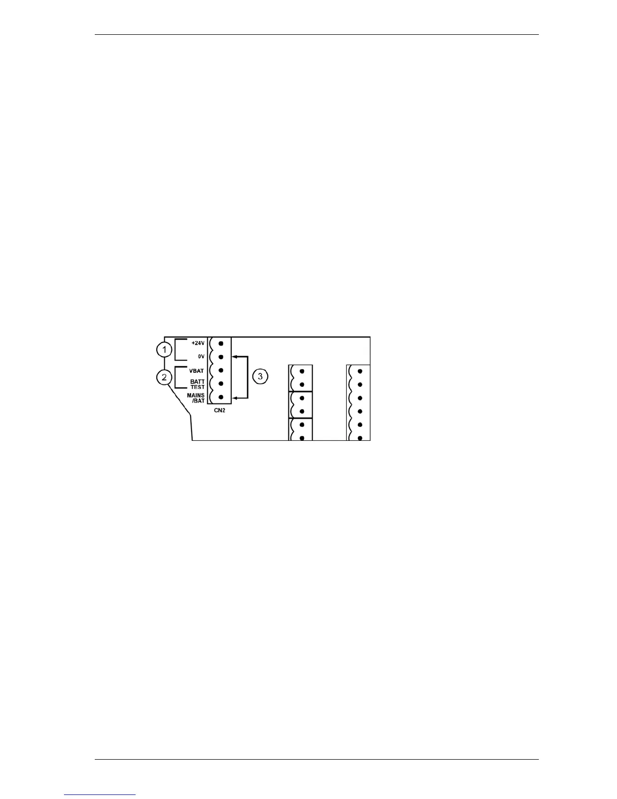
Connect the 24 VDC power supply to the 5-way connector (CN2) on the I/O board under the control panel as
shown in Figure 3-2.
1. External Power
Supply
2. No Connection
3. Link
Figure 3-2: 24 VDC connection for VFT Detectors
The MAINS/BAT terminal must be linked to 0 V. Failure to do so may result in a Mains Fault. The VBAT and
BATT TEST terminals should be left unconnected.
Ensure that in the Configuration menu, the STANDBY parameter is set to 0. For more information about
Configuration mode, refer to Section 5.3.4.
For use in UL/ULCFire Alarm Application, refer to Appendix F.
Grounding and Fuse Protection
An M5 chassis earthing stud is provided for the grounding of the unit using a suitable gauge of wire or earth
braiding (0.75 mm² minimum) to a primary earth point (i.e. copper water pipe or an earth-stake etc.). This
chassis earth should be connected on all DC powered installations.

 Loading...